
Abnormal detection device and method for electromagnetic brake

An electromagnetic brake and anomaly detection technology, which is applied in the direction of measuring devices, motor generator testing, measuring electricity, etc., can solve the problem of being unable to determine whether the electromagnetic brake is open or closed, the user cannot obtain fault information in time, and the motor electromagnetic brake is not known. work status etc.

Active Publication Date: 2021-09-14
重庆智能机器人研究院 +1
View PDF8 Cites 0 Cited by
  • Summary
  • Abstract
  • Description
  • Claims
  • Application Information

AI Technical Summary

Problems solved by technology

[0003] However, in the prior art, only a control signal to open or close the electromagnetic brake of the motor can be issued, but it is impossible to determine whether the electromagnetic brake is indeed opened or closed.
The user does not know the specific working status of the electromagnetic brake of the motor. When the electromagnetic brake device fails, the user cannot obtain the fault information in time, which poses a safety hazard.

Method used


Image

  • Abnormal detection device and method for electromagnetic brake
  • Abnormal detection device and method for electromagnetic brake
  • Abnormal detection device and method for electromagnetic brake

Examples


Embodiment Construction

[0051] In order to understand the above-mentioned purpose, features and advantages of the present invention more clearly, the present invention will be further described in detail below in conjunction with the accompanying drawings and specific embodiments. It should be noted that, in the case of no conflict, the embodiments of the present invention, that is, the features in the embodiments may be combined with each other.

[0052]In the following description, many specific details are set forth in order to fully understand the present invention. However, the present invention can also be implemented in other ways different from those described here. Therefore, the protection scope of the present invention is not limited by the specific details disclosed below. EXAMPLE LIMITATIONS.

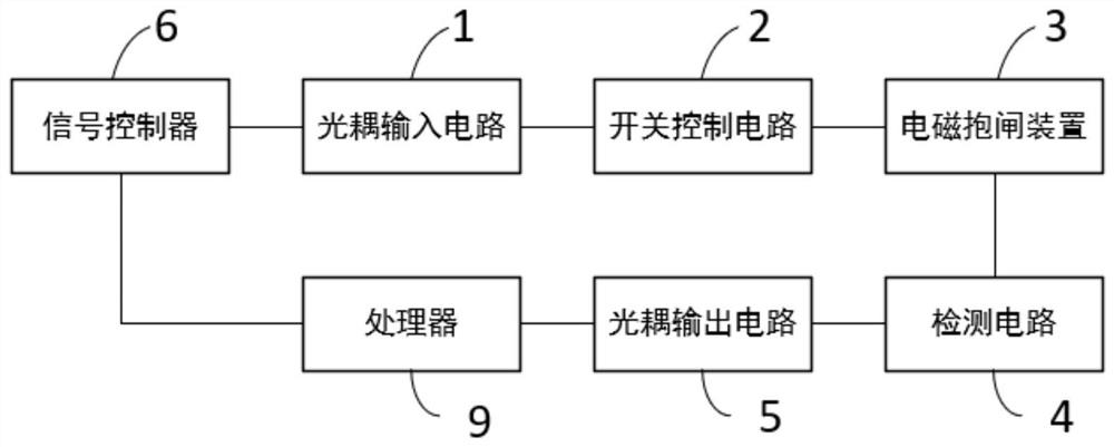
[0053] figure 1 A structural connection diagram of an abnormality detection device for an electromagnetic brake provided according to an embodiment of the present invention is shown.

[0054] Su...


PUM


Abstract

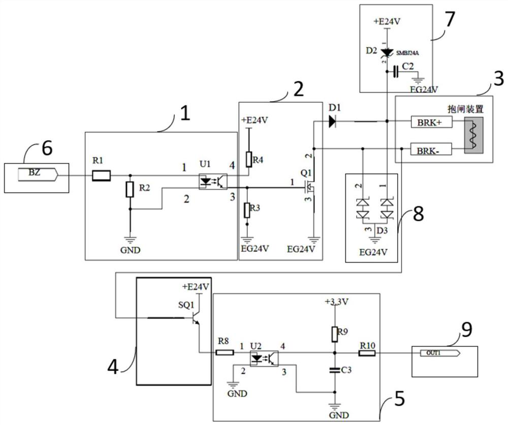
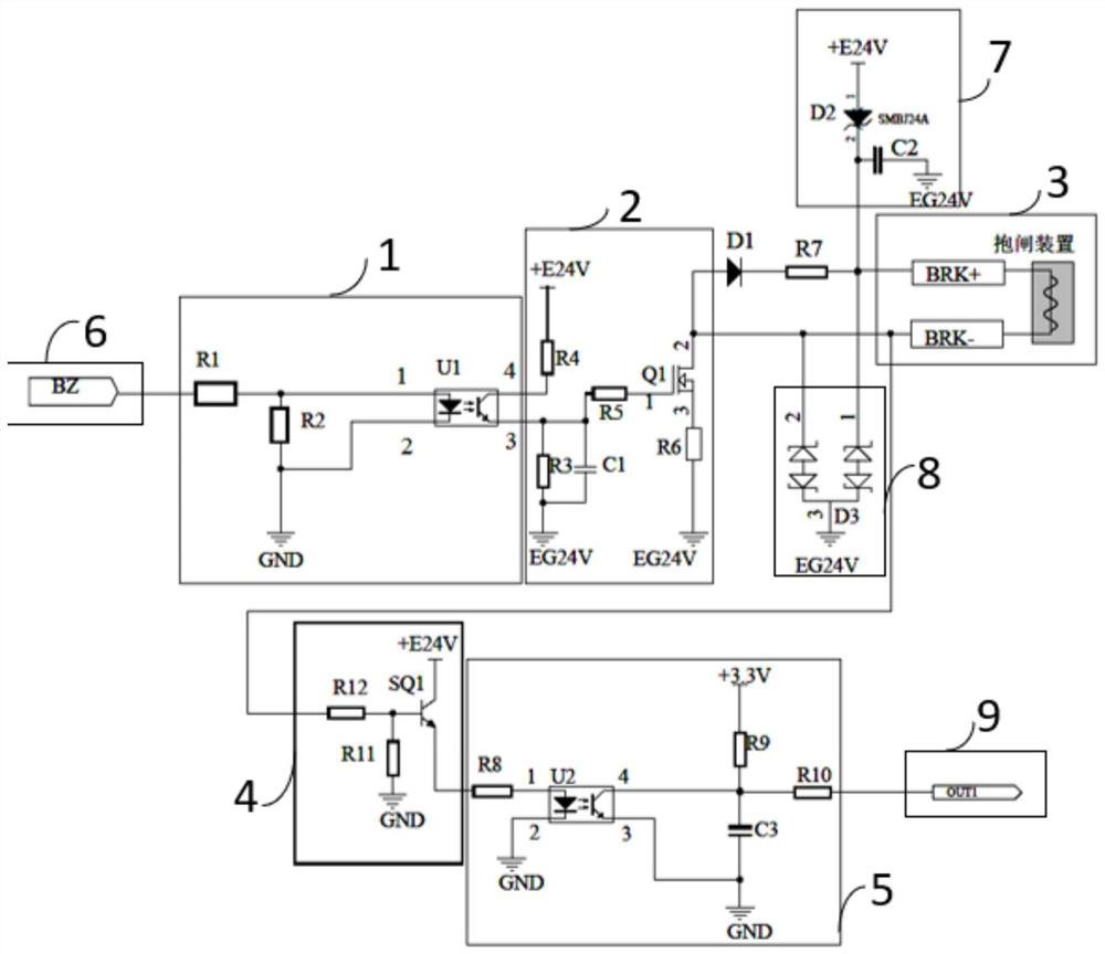
The invention discloses an abnormal detection device and method for an electromagnetic brake, and relates to the technical field of electromechanical control. Including signal controller, optocoupler input circuit, switch control circuit, detection circuit, optocoupler output circuit and processor; signal controller, optocoupler input circuit, switch control circuit, electromagnetic brake device, detection circuit and optocoupler output circuit Connect in sequence, the processor is connected with the signal controller and the optocoupler output circuit, the processor controls the signal controller to send the control signal; the optocoupler input circuit couples the control signal into the switch control circuit; the switch control circuit controls the electromagnetic brake device according to the control signal The detection circuit detects the electromagnetic brake device and obtains a detection signal; the optocoupler output circuit couples the detection signal into the processor; the processor determines whether the electromagnetic brake device is abnormal according to the control signal and the detection signal. The present invention can accurately judge whether the state of the electromagnetic brake is abnormal according to the detection signal.

Description

technical field [0001] The invention relates to the technical field of electromechanical control, in particular to an abnormal detection device and method for an electromagnetic brake. Background technique [0002] With the steady advancement of the "Made in China 2025" plan, industrial robots are being used on a large scale. Taking a six-joint industrial robot as an example, there is at least one joint that can perform work against gravity. When the motor in the joint does not work, or when the industrial robot is not powered, in order to ensure that the joint of the industrial robot does not sag, the motor with a brake is usually selected as the driving motor. In the industrial robot industry, the electromagnetic brake is generally used The motor of the gate is used as the driving motor of the industrial robot. [0003] However, in the prior art, only a control signal to open or close the electromagnetic brake of the motor can be issued, but it is impossible to determine...

Claims


Application Information

Patent Timeline
Patent Type & Authority Patents(China)
IPC IPC(8): G01R31/00G01R31/54G01R31/34
CPCG01R31/00G01R31/34G01R31/50
Inventor 曹祥杨海滨王旭丽郑登华
Owner 重庆智能机器人研究院
Learn More