
Low resistance object explaining and imaging method and system based on reflection coefficient analysis

A technology of reflection coefficient and imaging method, applied in the field of geotechnical exploration, can solve the problems such as the inability to accurately determine the scale of low-resistance anomalies, the inability to accurately identify the boundaries of low-resistance anomalies, and the need to improve the resolution of detection results. The effect of improving accuracy

Active Publication Date: 2019-10-15
SHANDONG UNIV
View PDF11 Cites 8 Cited by
  • Summary
  • Abstract
  • Description
  • Claims
  • Application Information

AI Technical Summary

Problems solved by technology

[0004] According to the knowledge of the inventor, in the current high-density electrical prospecting work, due to the influence of factors such as the accuracy of inversion results and interpolation grid density, the resolution of the detection results still needs to be improved
For example, the boundaries of low-resistivity anomalies in the formation cannot be accurately identified, which leads to the inability to accurately determine the scale of low-resistivity anomalies; different low-resistivity anomalies that are close to each other but isolated from each other will be represented as one in the final image. In the overall low-resistivity area, important factors such as the boundary, quantity and scale of low-resistivity anomalies in each formation cannot be accurately determined

Method used


Image

  • Low resistance object explaining and imaging method and system based on reflection coefficient analysis
  • Low resistance object explaining and imaging method and system based on reflection coefficient analysis
  • Low resistance object explaining and imaging method and system based on reflection coefficient analysis

Examples


Embodiment Construction

[0039] The present disclosure will be further described below in conjunction with the accompanying drawings and embodiments.

[0040] It should be noted that the following detailed description is exemplary and intended to provide further explanation of the present disclosure. Unless defined otherwise, all technical and scientific terms used herein have the same meaning as commonly understood by one of ordinary skill in the art to which this disclosure belongs.

[0041] It should be noted that the terminology used herein is only for describing specific embodiments, and is not intended to limit the exemplary embodiments according to the present disclosure. As used herein, unless the context clearly dictates otherwise, the singular is intended to include the plural, and it should also be understood that when the terms "comprising" and / or "comprising" are used in this specification, they mean There are features, steps, operations, means, components and / or combinations thereof.

...


PUM


Abstract

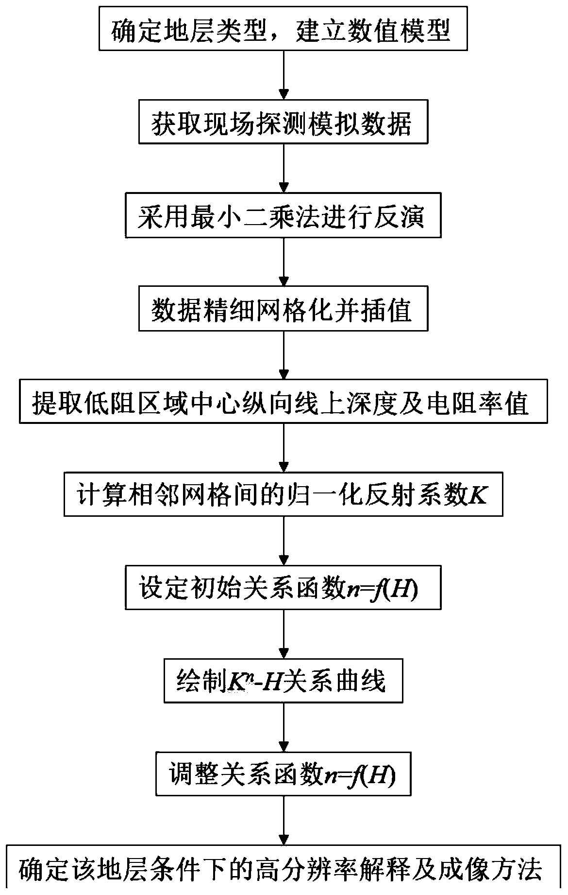
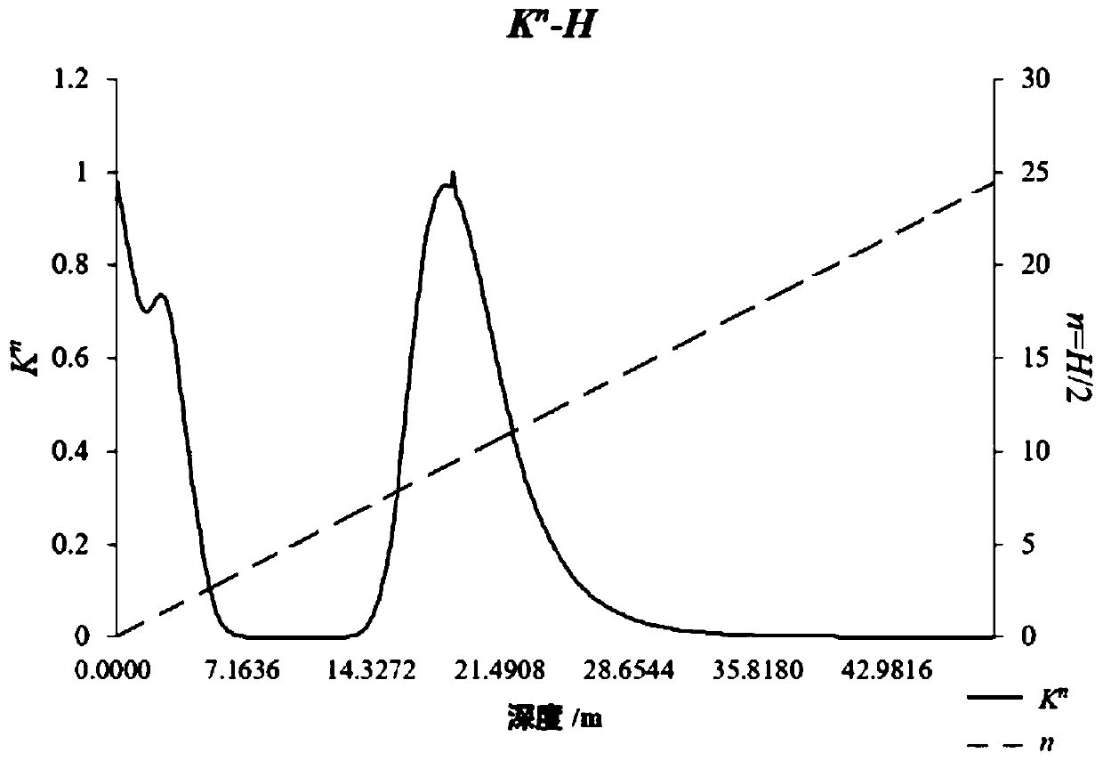
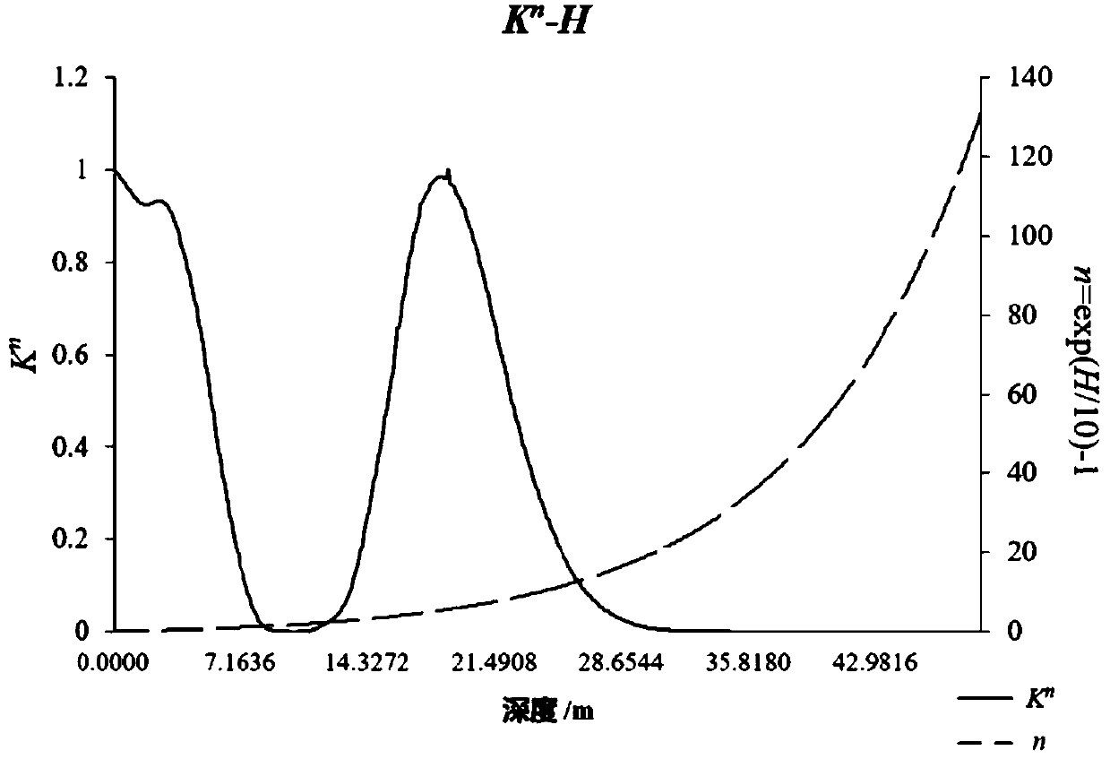
The invention provides a low resistance object explaining and imaging method and system based on reflection coefficient analysis. The method comprises the steps of simulating a formation condition tobe analyzed, setting a measuring line length and an electrode distance matched with each other by using a plurality of electrode arrangement modes, building a formation model, and collecting electrical prospecting data of an area to be detected; inverting the prospecting data, finely gridding original data acquired by inversion and using a Kriging method interpolation to image the grid data, and extracting the coordinate value and resistivity value of a grid node in a longitudinal direction of the center position of a low resistance object; computing the reflection coefficient of the extracteddata and normalizing the same, building a function of an amplification index and a depth value, computing the amplification index power of the reflection coefficient to serve as an influence value, drawing a relation curve of the influence value and the depth value, according to the waveform of the relation curve and the depth coordinate of a peak value, comparing original model data, and correcting the function; and adjusting a model parameter, and repeating the above-mentioned steps until the relation curve expresses the depth value of the low resistance body interface in the formation.

Description

technical field [0001] The disclosure belongs to the field of geotechnical exploration, and relates to a low-resistance body interpretation and imaging method and system based on reflection coefficient analysis. Background technique [0002] The statements in this section merely provide background information related to the present disclosure and do not necessarily constitute prior art. [0003] In near-surface geological exploration and investigation, various geophysical exploration methods are required. Due to the significant difference in the electrical properties of different geological bodies and the mature observation technology, electrical prospecting is a widely used method. Compared with conventional electrical prospecting, high-density electrical prospecting has the advantages of one-time completion of electrode layout, high degree of automation, large amount of collected information, and scanning measurement of various electrode arrangements. [0004] According ...

Claims


Application Information

Patent Timeline
IPC IPC(8): G01V3/38G01V3/08
CPCG01V3/08G01V3/38
Inventor 苏茂鑫王鹏薛翊国赵莹刘轶民邱道宏赵友超
Owner SHANDONG UNIV
Learn More