Broadband circularly polarized electromagnetic dipole antenna
An electromagnetic dipole, circularly polarized technology, used in antennas, resonant antennas, antenna grounding devices, etc., can solve the problems of narrow impedance bandwidth and axial ratio bandwidth, low gain, etc., to overcome the narrow impedance bandwidth and axial ratio bandwidth. , the effect of increasing the gain, widening the impedance bandwidth and the axial ratio bandwidth
- Summary
- Abstract
- Description
- Claims
- Application Information
AI Technical Summary
Problems solved by technology
Method used
Image

Examples
Embodiment 1
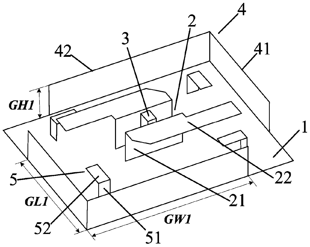
[0025] refer to figure 1 , a broadband circularly polarized electromagnetic dipole antenna, comprising a metal floor 1, an electromagnetic dipole 2, a feeding structure 3, an L-shaped metal plate 4 and four L-shaped parasitic branches 5.
[0026] The metal floor 1 adopts a rectangular structure, and L-shaped metal plates 4 are respectively fixed on the side edges where a pair of opposite corners are located, forming a metal back cavity with the metal floor 1. When the main body of the antenna radiates, due to electromagnetic coupling, the metal back The cavity is excited, which is equivalent to the second radiator, so a new impedance resonance frequency point and axial ratio resonance frequency point are introduced at high frequencies, effectively widening the impedance bandwidth and axial ratio bandwidth of the antenna at high frequencies, and at the same time The gain of the antenna can be increased. The L-shaped metal plate 4 is composed of a third rectangular metal plate ...
Embodiment 2
[0030] Embodiment 2, this embodiment has the same structure as Embodiment 1, only the following parameters have been adjusted:
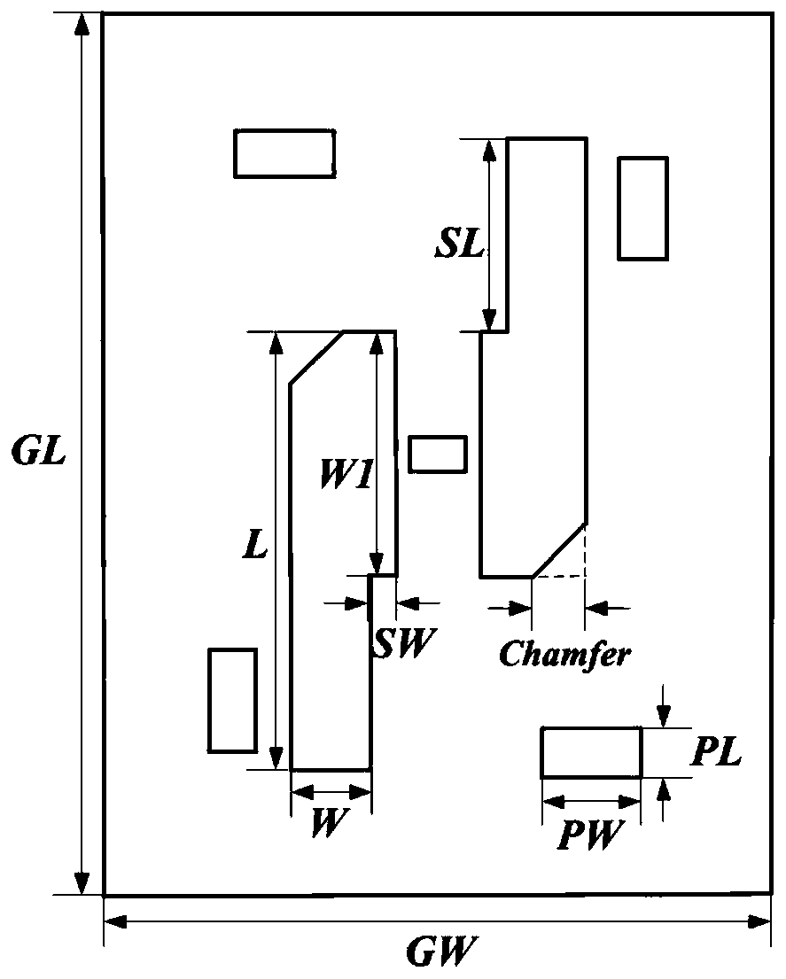
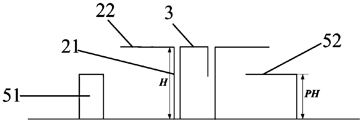
[0031] The size of the third rectangular metal plate 41 in the present invention is GL1×GW1, the value of GL1 is 180mm, the value of GW1 is 130mm, the size of the fourth rectangular metal plate 42 is GH1×GW1, and the value of GH1 is 29mm, The value of GW1 is 130mm; the length of the triangular cut corner included in the second rectangular metal plate 22 is Chamfer, and the value of Chamfer is 10.5mm, the size of the rectangular cut corner included in the second rectangular metal plate 22 is SL×SW, and the value of SL is 39mm, SW is 5mm; the size of the fifth rectangular metal plate 51 is PH×PW, the value of PH is 18mm, the value of PW is 9mm, the size of the sixth rectangular metal plate 52 is PL×PW, and PL is The value is 20mm, and the value of PW is 9mm.
Embodiment 3
[0033] Embodiment 3, the structure of this embodiment is the same as that of Embodiment 1, only the following parameters have been adjusted:
[0034] The size of the third rectangular metal plate 41 in the present invention is GL1×GW1, the value of GL1 is 190mm, the value of GW1 is 140mm, the size of the fourth rectangular metal plate 42 is GH1×GW1, and the value of GH1 is 30mm, The value of GW1 is 140mm; the length of the triangular cut corner included in the second rectangular metal plate 22 is Chamfer, and the value of Chamfer is 11.5mm. The size of the rectangular cut corner included in the second rectangular metal plate 22 is SL×SW, and the value of SL is 41mm, the value of SW is 6mm; the size of the fifth rectangular metal plate 51 is PH×PW, the value of PH is 19mm, the value of PW is 11mm, the size of the sixth rectangular metal plate 52 is PL×PW, and PL is The value is 21mm, and the value of PW is 11mm;
[0035] Below in conjunction with imitation experiment, technica...
PUM
| Property | Measurement | Unit |
|---|---|---|
| Rotation angle | aaaaa | aaaaa |
Abstract
Description
Claims
Application Information
 - R&D
- Intellectual Property
- Life Sciences
- Materials
- Tech Scout
- Unparalleled Data Quality
- Higher Quality Content
- 60% Fewer Hallucinations
Browse by: Latest US Patents, China's latest patents, Technical Efficacy Thesaurus, Application Domain, Technology Topic, Popular Technical Reports.
© 2025 PatSnap. All rights reserved.Legal|Privacy policy|Modern Slavery Act Transparency Statement|Sitemap|About US| Contact US: help@patsnap.com