
Heat dissipation device for mechanical and electrical equipment

A technology for heat dissipation devices and electromechanical equipment, which is applied to structural parts of electrical equipment, electrical components, and decoration through conduction and heat transfer. problems, to achieve a good cooling environment, save installation space, and improve cooling efficiency

Inactive Publication Date: 2019-10-15
SUZHOU MAICHUANG INFORMATION TECH
View PDF0 Cites 7 Cited by
  • Summary
  • Abstract
  • Description
  • Claims
  • Application Information

AI Technical Summary

Problems solved by technology

[0003] Mechanical and electrical equipment will generate a lot of heat during the working process. If the heat is not dissipated in time, it will not be conducive to the long-term operation of the mechanical and electrical equipment. In the prior art, the cooling device generally adopts air cooling or water cooling, and only using air cooling alone will not achieve To achieve a rapid cooling effect, and the use of water cooling often requires the installation of cooling pipes for water cooling inside the heat sink. The installation of cooling pipes will inevitably occupy the installation space of the electromechanical equipment body, which is not easy to install later.

Method used


Image

  • Heat dissipation device for mechanical and electrical equipment
  • Heat dissipation device for mechanical and electrical equipment
  • Heat dissipation device for mechanical and electrical equipment

Examples


Embodiment 1

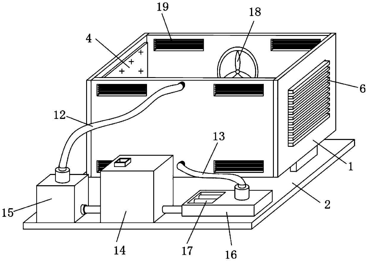
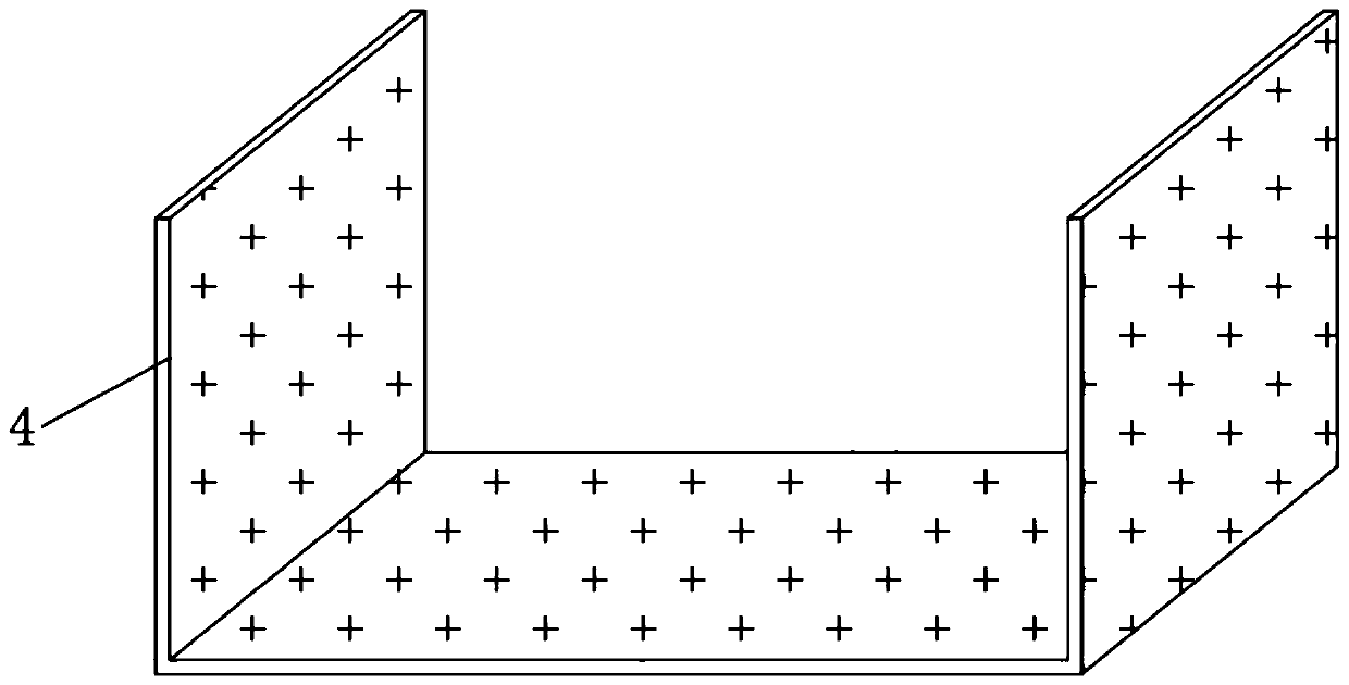
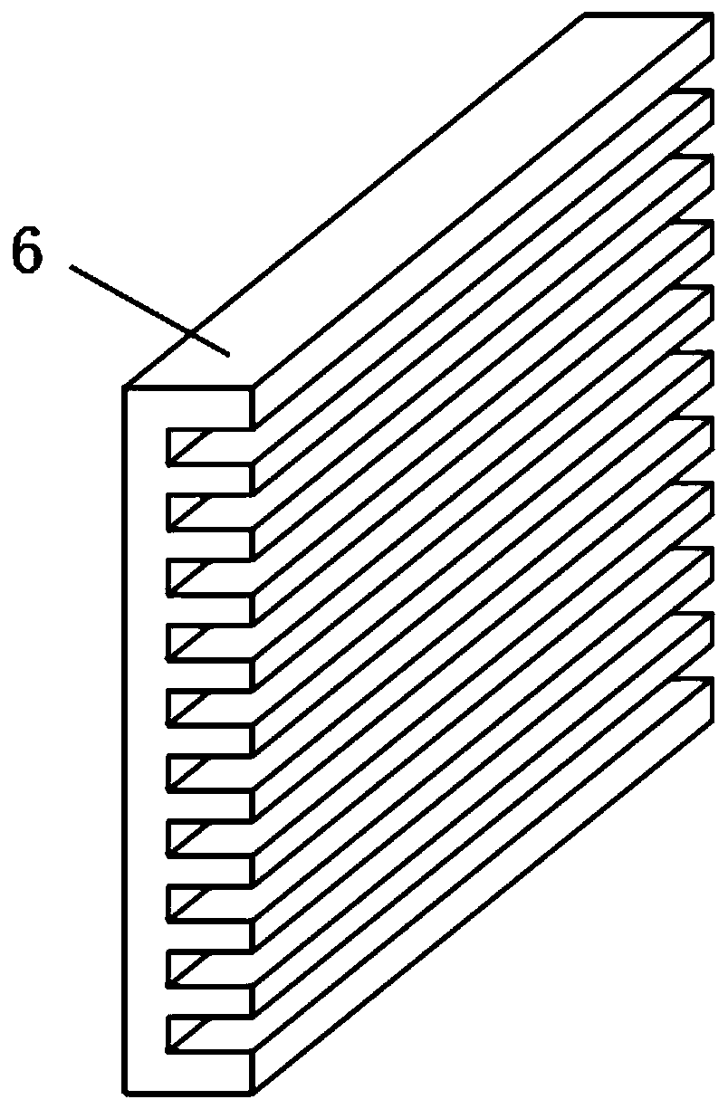
[0032] see Figure 1-3 , a heat dissipation device for electromechanical equipment, comprising a heat dissipation box 1 and a base 2 fixedly connected to the bottom of the heat dissipation box 1, the middle part of the lower end of the heat dissipation box 1 is fixedly connected to the base 2 through a support seat 3, and can be placed on the heat dissipation box 1 as required Install support plates on both sides of the bottom of the bottom respectively, which is conducive to improving the stability of the heat dissipation box 1. A U-shaped heat conducting plate 4 is sleeved inside the heat dissipation box 1, and the outer end side wall of the U-shaped heat conducting plate 4 is sealed with the heat dissipation box 1. Connected, the side walls on both sides of the inner bottom of the heat dissipation box 1 are provided with a plurality of strip-shaped heat dissipation chambers, and the strip-shaped heat dissipation chambers are embedded with heat dissipation strips 5, and the s...


PUM


Abstract

The invention discloses a heat dissipation device for mechanical and electrical equipment, belonging to the field of mechanical and electrical equipment. The heat dissipation device for mechanical andelectrical equipment includes a heat dissipation box and a base fixedly connected at the bottom of the heat dissipation box. The middle of the lower end of the heat dissipation box is fixedly connected to the base through a support seat. The heat dissipation box is internally sleeved with a U-shaped heat conducting plate. The outer side wall of the U-shaped heat conducting plate is in sealing connection with the heat dissipation box. Multiple strip-shaped heat dissipation cavities are arranged in the two side walls of the inner bottom of the heat dissipation box, and heat dissipation strips are embedded into the strip-shaped heat dissipation cavities. Rectangular heat dissipation cavities are arranged in the left and right side walls of the heat dissipation box, and heat dissipation plates are embedded into the rectangular heat dissipation cavities. Through the cooperation of the U-shaped heat conducting plate, the heat dissipation strips and the heat dissipation plates, the hot air in the heat dissipation box can be transferred out. Through the use of a heat dissipation fan, a water cooling circulation device and a flow channel, the heat dissipation and temperature reduction efficiency of the heat dissipation box is further improved, and a good temperature reduction and heat dissipation environment is provided for the mechanical and electrical equipment in the heat dissipation box.

Description

technical field [0001] The invention relates to the field of electromechanical equipment, and more specifically, relates to a heat dissipation device for electromechanical equipment. Background technique [0002] Electromechanical equipment generally refers to machinery, electrical appliances and electrical automation equipment. With the continuous improvement of people's living standards, people's demand for electromechanical equipment in daily life is increasing. From vehicles to various household appliances, computers, printers, etc. It has become an indispensable electromechanical product in people's life. [0003] Mechanical and electrical equipment will generate a lot of heat during the working process. If the heat is not dissipated in time, it will not be conducive to the long-term operation of the mechanical and electrical equipment. In the prior art, the cooling device generally adopts air cooling or water cooling, and only using air cooling alone will not achieve ...

Claims


Application Information

Patent Timeline
IPC IPC(8): H05K7/20
CPCH05K7/20136H05K7/20172H05K7/20218H05K7/20272H05K7/2039
Inventor 周皓
Owner SUZHOU MAICHUANG INFORMATION TECH
Learn More