Drilling device capable of avoiding debris residue for hardware tools machining

A technology of hardware tools and drilling devices, which is applied in the direction of metal processing equipment, metal processing machinery parts, positioning devices, etc., can solve the problems of wasting the working time of operators, splashing metal debris and dust, and reducing the efficiency of drilling, and achieves The fixed operation is simple and fast, and the effect of improving work efficiency

Inactive Publication Date: 2019-10-18
徐州兴隆工具科技股份有限公司
View PDF7 Cites 12 Cited by
  • Summary
  • Abstract
  • Description
  • Claims
  • Application Information

AI Technical Summary

Problems solved by technology

[0003] A Chinese patent discloses a drilling device for hardware processing. The authorized publication number is CN105817670A. This patented technology can solve the phenomenon of uneven holes when drilling hardware, improve work efficiency, and improve the service life of the workbench. However, When punching holes, dust splashes of metal scraps will be generated, and the splashed metal scraps will remain on the drilling machine console. Those skilled in the art provide a subject to solve the problems raised in the above-mentioned background technology
[0004] Operators are in an environment with flying debris and dust for a long time when drilling, which will cause damage to the human respiratory tract, and the flying debris will remain on the surface of the tool and the drilling machine operating table after falling. It is troublesome to clean up, wastes the working time of the operator, and reduces the working efficiency of drilling

Method used


Image

  • Drilling device capable of avoiding debris residue for hardware tools machining
  • Drilling device capable of avoiding debris residue for hardware tools machining
  • Drilling device capable of avoiding debris residue for hardware tools machining

Examples


Embodiment Construction

[0022] The following will clearly and completely describe the technical solutions in the embodiments of the present invention with reference to the accompanying drawings in the embodiments of the present invention. Obviously, the described embodiments are only some of the embodiments of the present invention, not all of them.

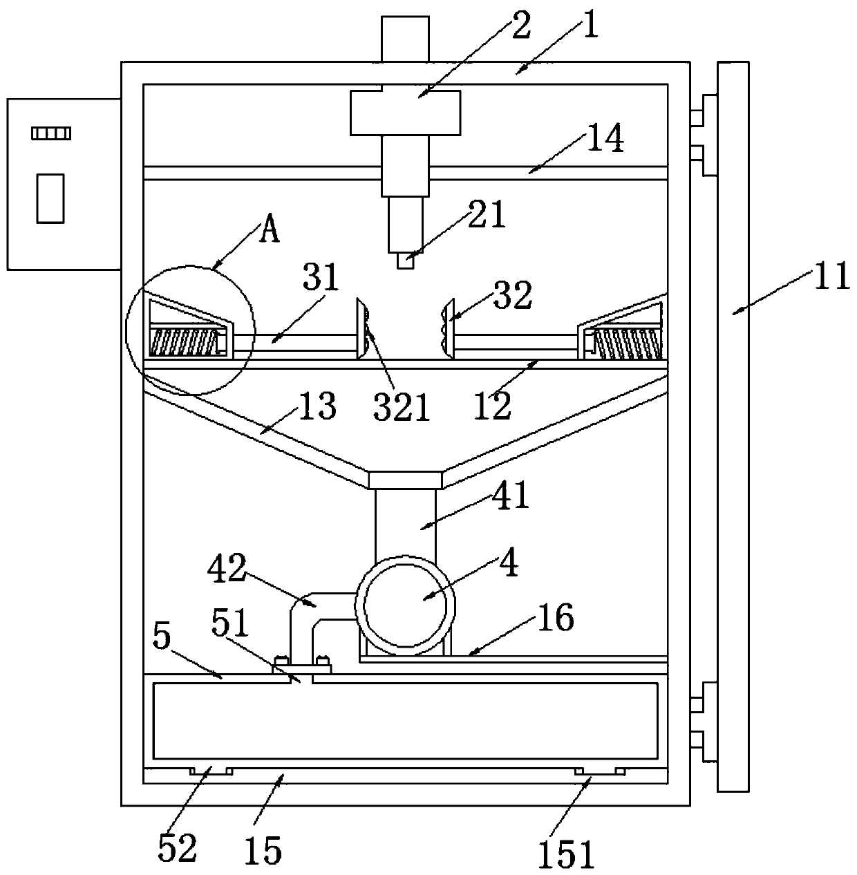
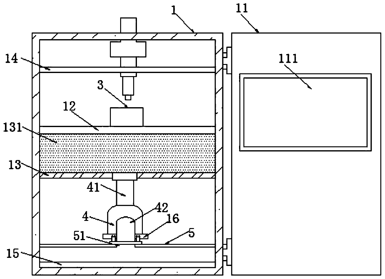
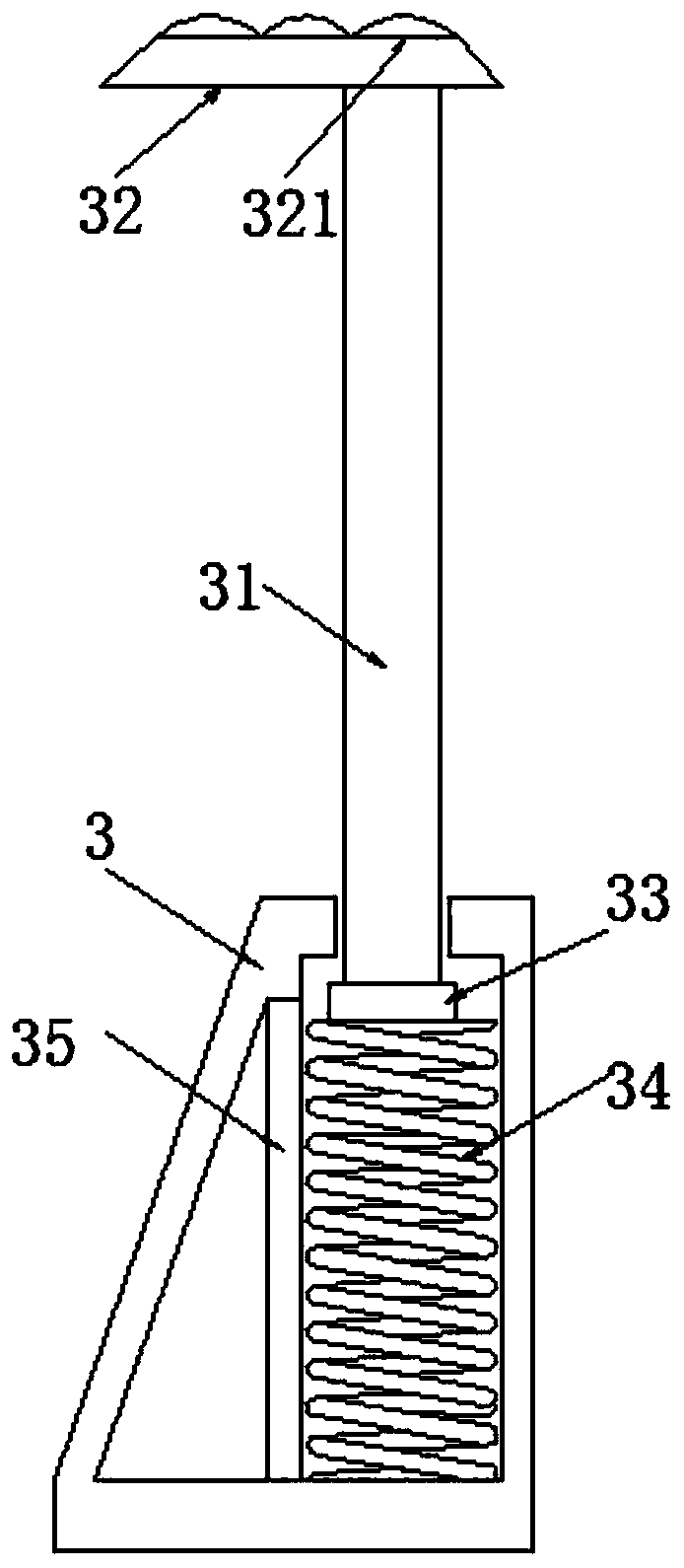
[0023] refer to Figure 1-4 , a subject of a drilling device for processing hardware tools to avoid debris residues, including a box body 1 and a drilling machine 2 fixedly connected to the top of the box body 1, the drilling machine 2 is provided with a punching head 21 at one end inside the box body 1, through The drilling machine 2 drives the punching cutter head 21 to rotate and punches the required workpiece. The drilling machine 2 drives the punching cutter head 21 to rotate as the prior art, and does not belong to the improvement of the program, so it will not be repeated here; the box body 1 The installation box 3 is fixedly connected to both si...


PUM


Abstract

The invention belongs to the field of drilling, and particularly relates to a drilling device capable of avoiding chip residue for hardware tools machining. Aiming at solving the problem that chips are left during drilling in the prior art, according the scheme, the drilling device comprises a box body and a drilling machine fixedly connected to the top of the box body, wherein an output end of the drilling machine is fixedly connected with a drilling tool bit, and mounting boxes are fixedly connected to the two sides of the inner wall of the box body; push rods are slidably connected into themounting boxes, and one sides of the push rods are fixedly connected with clamping plates; and a placing plate is fixedly connected to the inner wall of the box body, the placing plate is positionedright below the mounting boxes, and guide plates which are fixedly connected to the two sides of the inner wall of the box body are arranged right below the placing plate. The chips directly enters atwining pipe through the influence of the guiding of the guide plates and the twitching of an exhaust fan, then the chips are discharged into a collecting box through a discharging pipe for collection, and then the collecting box is taken out to pour the chips out, so that chips generated during drilling are treated in the first time.

Description

technical field [0001] The invention relates to the technical field of drilling, in particular to a drilling device for hardware tool processing which avoids debris residue. Background technique [0002] Drilling machine is a general term for machinery and equipment that leaves cylindrical holes or holes on the target by means of rotary cutting or rotary extrusion using tools that are harder and sharper than the target. By drilling precision parts , To achieve the desired effect, the drilling machine has a semi-automatic drilling machine and a fully automatic drilling machine. [0003] The Chinese patent discloses a drilling device for hardware processing, and the authorized publication number is CN105817670A. This patented technology can solve the phenomenon of uneven holes in the drilling of hardware, improve work efficiency, and improve the service life of the workbench, but Metal chip dust splashes will be generated during drilling, and the splashed metal chip will rema...

Claims


Application Information

Patent Timeline
Patent Type & Authority Applications(China)
IPC IPC(8): B23B39/00B23Q3/06B23Q11/00
CPCB23B39/00B23Q3/06B23Q11/0046B23Q11/0067
Inventor 丛福龙
Owner 徐州兴隆工具科技股份有限公司
Why Eureka
Try Eureka