A reverse circulation drilling system and reverse circulation drilling method

A reverse circulation and drilling technology, applied in drilling equipment and methods, drilling equipment, wellbore/well components, etc., can solve the problems of high cost and production difficulty, achieve the goal of reducing drilling friction, reducing cost and improving life Effect

Active Publication Date: 2020-09-11
SICHUAN UNIVERSITY OF SCIENCE AND ENGINEERING
View PDF9 Cites 0 Cited by
  • Summary
  • Abstract
  • Description
  • Claims
  • Application Information

AI Technical Summary

Problems solved by technology

However, due to the high cost and production difficulty of double-walled drill pipes, equipment and tools such as surface rotary head blowout preventers, downhole reverse circulation motors, well deviation monitoring tools, downhole blowout preventers and drill bits are also required to match double-wall drill pipes. , which limits the application of the technique

Method used


Image

  • A reverse circulation drilling system and reverse circulation drilling method
  • A reverse circulation drilling system and reverse circulation drilling method
  • A reverse circulation drilling system and reverse circulation drilling method

Examples


Embodiment

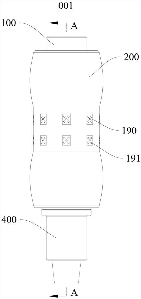
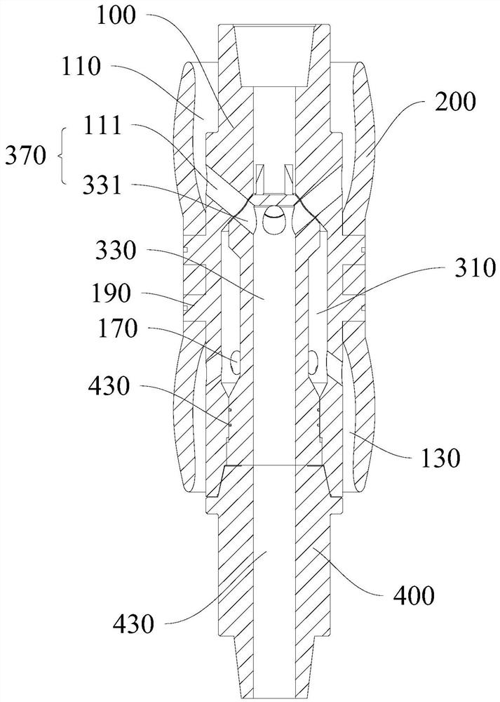
[0051] This embodiment provides a reverse circulation drilling system, please refer to figure 1 , figure 2 , image 3 and Figure 4 , this reverse circulation drilling system includes a casing 600 , a circulation channel switching nipple 001 , a first drill pipe 710 , a second drill pipe 730 and a drill bit 800 .

[0052] The casing 600 is lowered into the well after the drilling of the previous wellbore is completed, and the drilling wall is reinforced with cement, and the inside of the casing 600 is formed as a working wellbore 610 for the lower open-hole drilling.

[0053] The reverse circulation drilling circulation channel switching nipple 001 includes an upper joint 100 , a rubber plug 200 , a reversing mandrel 300 and a lower joint 400 , wherein the rubber plug 200 is sleeved on the outside of the upper joint 100 .

[0054] see Figure 11 and Figure 12 , the reverse circulation drilling circulation channel switching nipple 001 is installed in the working wellbore...

Embodiment 2

[0077] This embodiment provides a reverse circulation drilling method, please refer to Figure 11 and Figure 12 , this reverse circulation drilling method is implemented using the reverse circulation drilling system provided by Embodiment 1, including steps:

[0078] a. Run the casing 600 for cementing after the completion of the last drilling;

[0079] b. Statistically drill 800 feet of drill bits at different depths in the drilled block, and use the average drill bit 800 feet as the estimated drilling depth data D for each drilling trip i , select the drill bit 800 and the second drill rod 730;

[0080] c. Run into the drilling tool, and the drilling depth reaches L i At the same time, install the circulation channel switch sub-joint 001 at the end of the second drill pipe 730, install the first drill pipe 710 at the other end of the circulation channel switch sub-joint 001, and continue drilling to extend the drill bit 800 to the bottom of the well, wherein, L i than D...


PUM


Abstract

The invention provides a reverse circulation well drilling system and a reverse circulation well drilling method and belongs to the field of well drilling tools. The reverse circulation well drillingsystem comprises a sleeve, a circulation channel switching nipple, a first drill stem, a second drill stem and a drill bit. A work shaft is formed in the sleeve. The circulation channel switching nipple is provided with an upper connector and a rubber plug and arranged in the work shaft. An inflow channel and an outflow channel are formed in the upper connector in a spaced manner. The first drillstem is connected with one end of the circulation channel switching nipple , and the second drill stem is connected with the other end of the circulation channel switching nipple. A drilling fluid supply channel is formed in the first drill stem, and a fluid outlet section is formed outside the first drill stem. A drilling fluid recycling channel is formed in the second drill stem. A fluid inlet section is formed outside the second drill stem. The rubber plug is sealed with the inner wall of the work shaft and isolates the fluid outlet section and the fluid inlet section. The fluid inlet section and the drilling fluid recycling channel communicate in the drilled well. By the adoption of the reverse circulation well drilling system and the reverse circulation well drilling method, ground equipment does not need change and adjustment, no influence is caused on the conventional well drilling construction technology, the shaft bottom open hole section annulus is free of rock fragments, drilling friction is lowered, speed improvement and cost reduction are facilitated, and well drilling safety is guaranteed.

Description

technical field [0001] The invention relates to the field of drilling tools, in particular to a reverse circulation drilling system and a reverse circulation drilling method. Background technique [0002] Reverse circulation drilling technology is a drilling technology developed to solve the drilling problems of low pressure, low permeability and easy leakage oil and gas reservoirs, reduce drilling friction, protect reservoirs and improve drilling safety. This technology generally uses double-walled drill pipe. By injecting circulating medium into the drill pipe annulus, after cleaning the drill bit and carrying cuttings at the bottom of the hole, the drilling fluid carrying cuttings flows into the inner channel of the drill pipe and returns to the ground. During the drilling process , Broken cuttings do not enter the drill pipe and borehole annulus, the annulus is purified drilling fluid with stable performance and stable pressure, which can effectively protect the reservoi...

Claims


Application Information

Patent Timeline
Patent Type & Authority Patents(China)
IPC IPC(8): E21B7/00E21B21/12E21B17/02E21B10/60E21B21/06
CPCE21B7/00E21B10/60E21B17/02E21B21/06E21B21/12
Inventor 胡中志朱宽亮王在明徐小峰周岩李云峰宋巍李莹
Owner SICHUAN UNIVERSITY OF SCIENCE AND ENGINEERING
Why Eureka
Try Eureka