Mechanical pile forming device for base-expanded poured foundation pile and pile forming method thereof

A mechanical and pile-forming technology, which is applied in the direction of drilling equipment and methods, sheet pile walls, earthwork drilling and mining, etc., can solve the problems of difficult excavation in hard soil layers, low construction efficiency of bottom-expanding cast-in-place piles, etc., and achieve the goal of construction High efficiency, reduced construction costs, and small disturbance effects

Pending Publication Date: 2019-10-18
范茂丰 +1
View PDF0 Cites 3 Cited by
  • Summary
  • Abstract
  • Description
  • Claims
  • Application Information

AI Technical Summary

Problems solved by technology

[0004] The purpose of the present invention is to solve the low construction efficiency of the bottom-expanding cast-in-place foundation pile; when the bottom-expanding cast-in-place foundation pile is manually excavated, it is difficult to excavate the harder soil layer; Influence; manual excavation of the bottom-expanding cast-in-place foundation pile disturbs the pile bottom soil and other issues; improving the quality of the pile and improving the bearing capacity of the foundation pile; providing a mechanical pile-forming device and a pile-forming method for the bottom-expanding cast-in-place foundation pile

Method used


Image

  • Mechanical pile forming device for base-expanded poured foundation pile and pile forming method thereof
  • Mechanical pile forming device for base-expanded poured foundation pile and pile forming method thereof
  • Mechanical pile forming device for base-expanded poured foundation pile and pile forming method thereof

Examples


Embodiment Construction

[0031] Specific embodiments of the present invention will be described in detail below in conjunction with the accompanying drawings.

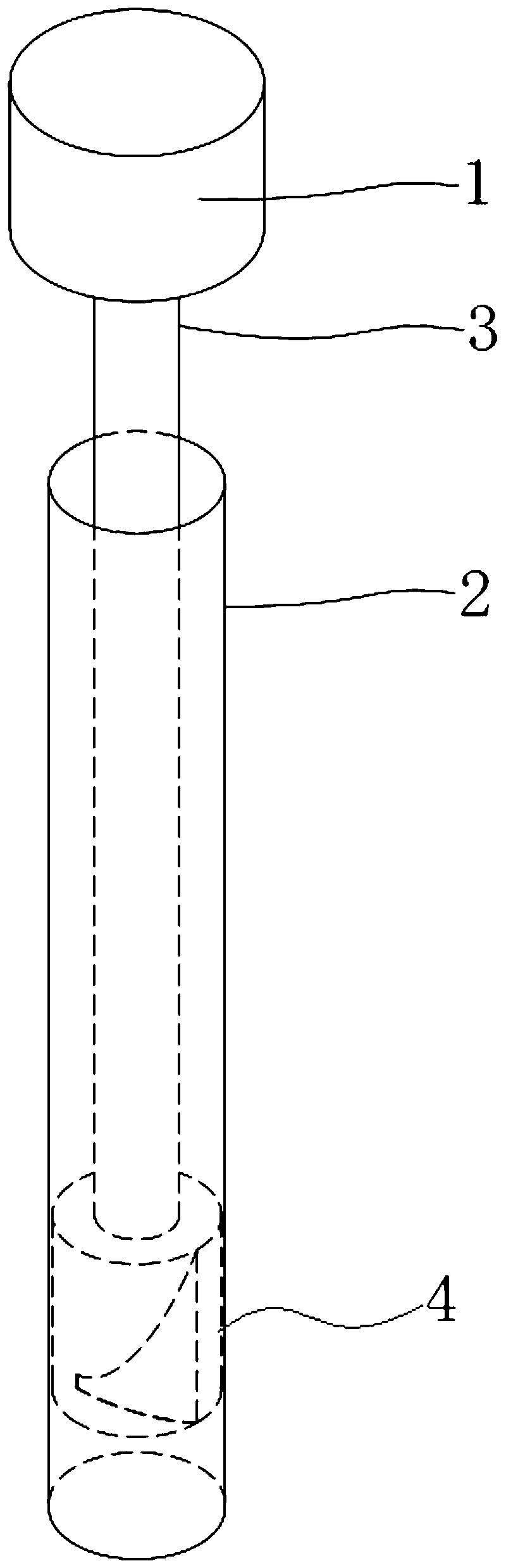
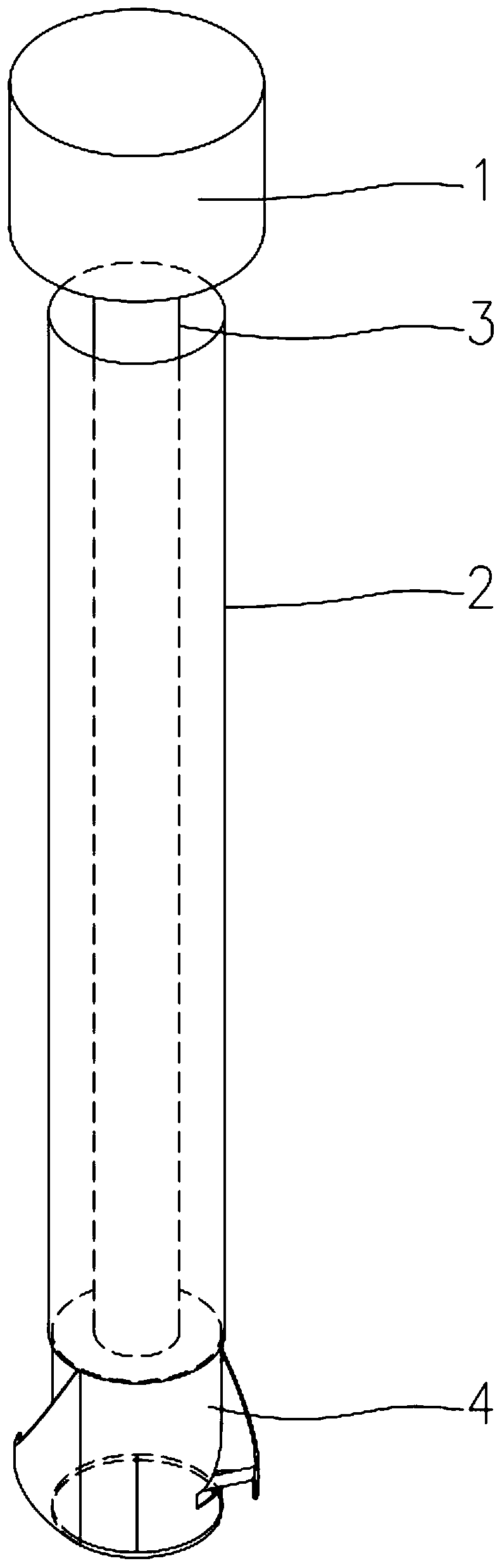
[0032] attached by figure 1 , 2 Shown: a mechanical pile-forming device for bottom-expanding cast-in-situ piles, the device includes a power rotating head 1 that provides power for the rotating shaft, a rotating transmission shaft 3 (hollow steel pipe) connected under the power rotating head 1, and a set At the steel pipe casing 2 on the outside of the rotating transmission shaft 3, a reaming drill bit 4 that is connected to the rotating transmission shaft 3 ends.

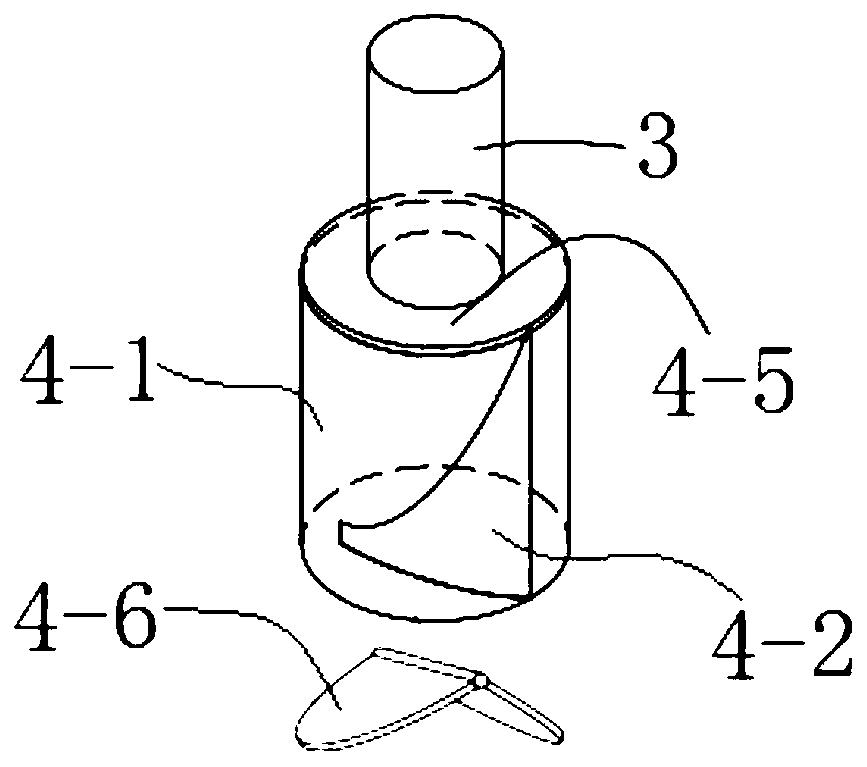
[0033] attached by image 3 , 4 As shown: the bottom reaming drill bit 4 is composed of a barrel-shaped bottom reaming drill bit main body 4-1, a mechanical opening and reaming blade 4-2, a hydraulic device for opening and closing the reaming blade 4-3, a hydraulic control conduit 4-4, and a drill top plate 4-5 and the mechanical opening and closing bottom plate 4-6, the two me...


PUM


Abstract

The invention relates to a mechanical pile forming device for a base-expanded poured foundation pile and a pile forming method thereof. The mechanical pile forming device for the base-expanded pouredfoundation pile comprises a powered rotating head providing power for a rotary shaft, a rotating transmission shaft connected below the powered rotating head, a steel pipe protective casing installedon the outer side of the rotating transmission shaft in a sleeving manner and a bottom-expanding drill bit connected to an end of the rotating transmission shaft. The mechanical pile forming method comprises the steps that hole drilling operation of a pile body A of the foundation pile is conducted; the bottom-expanding drill bit goes deep into the hole bottom along the interior of the steel pipeprotective casing, and hole expanding operation is conducted; a pre-lashed pile body steel bar reinforcement cage is fed from top to bottom along the interior of the steel pipe protective casing; foundation pile concrete is poured, and meanwhile, the steel pipe protective casing is elevated; and base-expanded poured foundation pile construction is conducted, and the base-expanded end B of the base-expanded poured foundation pile is formed below the pile body A of the foundation pile. The mechanical pile forming device for the base-expanded poured foundation pile has the advantages that the influence of underground water on pile forming is obstructed, the pile forming quality of the base-expanded poured foundation pile is improved, the foundation construction cost of projects is lowered, and construction efficiency is high.

Description

technical field [0001] The invention relates to a mechanical pile-forming device and a pile-forming method for bottom-expanding cast-in-situ piles, which belong to the field of construction engineering structures. Background technique [0002] The mechanically drilled bored pile is a relatively new construction method, which is an improvement and innovation of the bored pile. It utilizes drilling to reach the required load-bearing layer, and then replaces the pile end with a special drill bit to expand the diameter of the pile end, so that the ultimate bearing capacity of the pile has a greater increase than that of the cast-in-place pile without an enlarged head. The design requires that the diameter of the pile body be enlarged by more than 1.5 times. In theory, the ultimate bearing capacity of the pile will be more than 2 times that of the pile without the enlarged head. The steel pipe casing is used as a construction protection measure for the mechanically drilled botto...

Claims


Application Information

Patent Timeline
Patent Type & Authority Applications(China)
IPC IPC(8): E21B7/28E21B10/32E02D5/38E02D5/44
CPCE02D5/385E02D5/44E21B7/28E21B10/322
Inventor 黄永存范茂丰
Owner 范茂丰
Why Eureka
Try Eureka