Oil pumping unit system with multiple sections of steam injection packer parts

A technology of pumping unit and packer, which is applied in sealing/package, wellbore/well parts, production fluid, etc. It can solve the problems of complex structure, steam can not be injected to the bottom of the well, and the effect of gas injection can be reduced. , to achieve high mechanical efficiency, improve vertical flow and efficiency, and save energy

Active Publication Date: 2019-10-18
胜利方兰德石油装备股份有限公司
View PDF8 Cites 7 Cited by
  • Summary
  • Abstract
  • Description
  • Claims
  • Application Information

AI Technical Summary

Problems solved by technology

The valve ball of the pump with this structure is suspended on the upper part of the ball seat with shear nails and shear rods to form a steam injection channel, and the structure is complex
The other is to inject gas through the outside of the pump barrel. The steam in this structure cannot be injected to the bottom of the well, which greatly reduces the effect of gas injection.

Method used


Image

  • Oil pumping unit system with multiple sections of steam injection packer parts
  • Oil pumping unit system with multiple sections of steam injection packer parts
  • Oil pumping unit system with multiple sections of steam injection packer parts

Examples


Embodiment Construction

[0069] In order to make the purpose, technical solution and advantages of the present invention clearer, the technical solution of the present invention will be described in detail below. Apparently, the described embodiments are only some of the embodiments of the present invention, but not all of them. Based on the embodiments of the present invention, all other implementations obtained by persons of ordinary skill in the art without making creative efforts fall within the protection scope of the present invention.

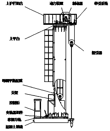
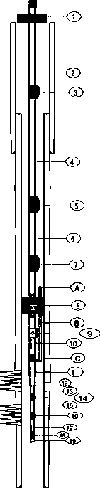
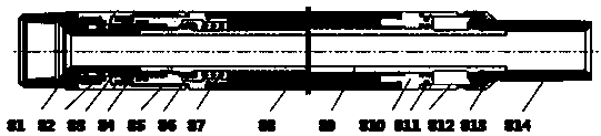
[0070] see Figure 1-Figure 5 As shown, a pumping unit system with multi-stage steam injection packer includes the pumping unit main body, gas injection thermal recovery pump and packer assembly. The pumping unit main body is connected with the gas injection thermal recovery Oil well pump connection, gas injection thermal recovery oil well pump and packer assembly are connected through hands-off joints,

[0071] The main body of the pumping unit includes: conc...


PUM


Abstract

The invention discloses an oil pumping unit system with multiple sections of steam injection packer parts. The oil pumping unit system comprises an oil pumping unit body, a steam injection thermal production oil pump and a packer assembly. The oil pumping unit body is connected with the steam injection thermal production oil pump through a traction system of the oil pumping unit body. The steam injection thermal production oil pump is connected with the packer assembly through a release sub. The packer assembly comprises the release sub, a first oil discharging pipe, a first side sealing spindle, a second oil discharging pipe, a second side sealing spindle, a third oil discharging pipe, a third side sealing spindle, a packer body, a one-way valve, a first spraying head, a second spraying head, a sealing ring, a fourth oil discharging pipe, a third side sealing spindle, a fifth oil discharging pipe, a fourth side sealing spindle, a third spraying head, a ventilation pipe, a cable inletguiding part and a side gas pipeline.

Description

technical field [0001] The invention relates to the technical field of pumping units, in particular to a pumping unit system with multi-stage steam injection seals. Background technique [0002] In recent years, as the world's energy problems have become increasingly prominent, energy conservation of pumping units has become a major concern of people. Various domestic manufacturers and research institutes continue to apply new technologies, through structural optimization design and improved balance methods, etc., to achieve pumping units. The purpose of energy saving of oil pumps is to reduce energy consumption and reduce oil production costs. A batch of new pumping units have been put into oil field production in the past few years. How to ensure high pumping efficiency, long life of pumping units, small dynamic load, and Quantity stability is also a problem that pumping units are currently facing. [0003] As a key component of the downhole pumping unit system, the packe...

Claims


Application Information

Patent Timeline
Patent Type & Authority Applications(China)
IPC IPC(8): E21B43/00E21B43/24E21B47/00E21B23/06E21B33/126E21B33/127E21B19/084
CPCE21B19/084E21B23/06E21B33/126E21B33/127E21B43/126E21B43/24E21B47/00
Inventor 付少彬赵玉刚王海洋
Owner 胜利方兰德石油装备股份有限公司
Why Eureka
Try Eureka