Bearing fault detection device and detection method

A fault detection and bearing technology, which is applied in the direction of measuring devices, testing of mechanical components, testing of machine/structural components, etc., can solve problems such as difficulty in fault feature extraction, low accuracy, and complex signal processing in fault diagnosis methods, and achieve Strong anti-interference ability, strong sensitivity and high measurement accuracy

Pending Publication Date: 2019-10-18
LINGNAN NORMAL UNIV
View PDF0 Cites 2 Cited by
  • Summary
  • Abstract
  • Description
  • Claims
  • Application Information

AI Technical Summary

Problems solved by technology

[0005] In order to solve the problems of difficult feature extraction, complex signal processing and low accuracy of the existing bearing fault diagnosis methods, the present invention provides a bearing fault detection device and detection method, which can perform non-contact detection and is easy to operate. Strong anti-interference ability to extract fault features, high sensitivity and high measurement accuracy

Method used


Image

  • Bearing fault detection device and detection method
  • Bearing fault detection device and detection method
  • Bearing fault detection device and detection method

Examples


Embodiment 1

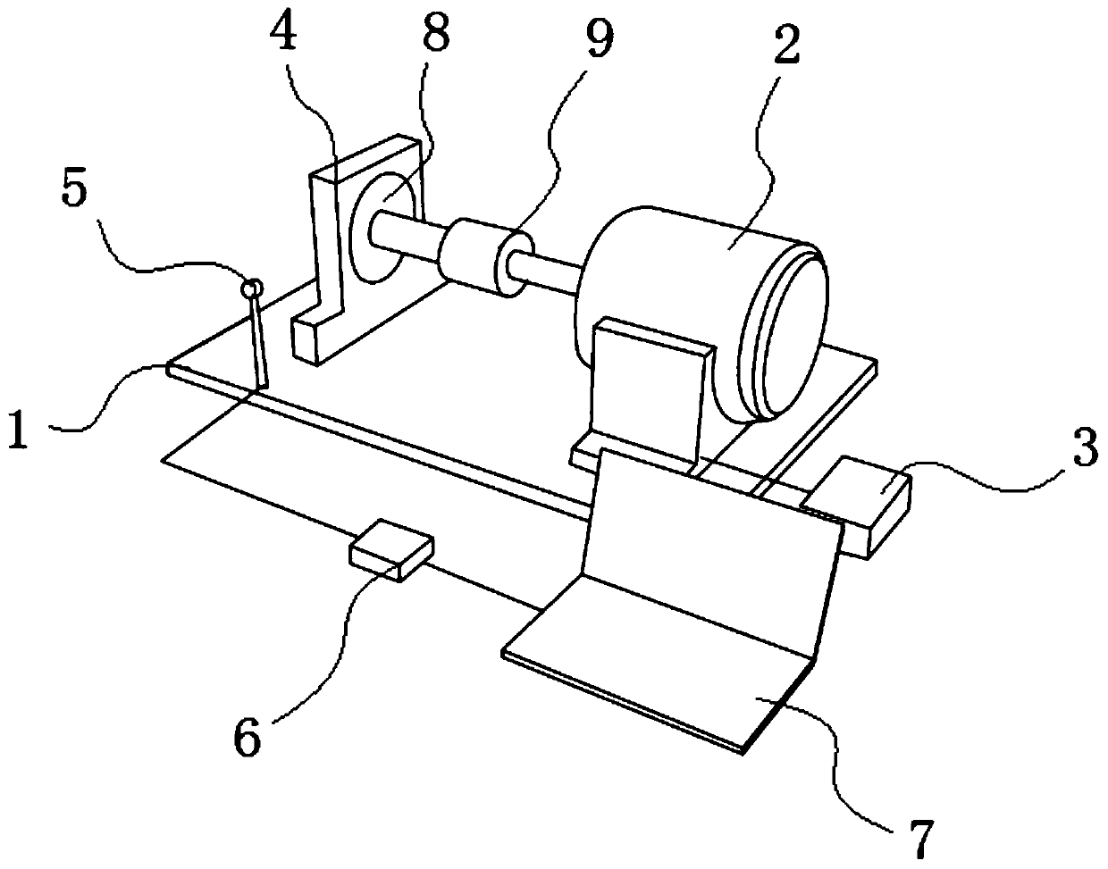
[0036] Such as figure 1 As shown, a bearing fault detection device includes a workbench 1, a DC geared motor device, a bearing seat 4, a laser self-mixing interference device 5, a data acquisition and analysis device 6, and a computer 7. The DC geared motor device, the bearing The seat 4 and the laser self-mixing interference device 5 are all arranged on the worktable 1, the bearing 8 to be detected is installed on the bearing seat 4, the DC geared motor device is connected to the bearing 8, and the laser The self-mixing interference device 5 is arranged on the side of the bearing housing 4, the laser self-mixing interference device 5 is connected to the data acquisition and analysis device 6, and the data acquisition and analysis device 6 is connected to the computer 7. The present invention overcomes the To solve the problems of traditional bearing fault diagnosis methods relying too much on expert experience, difficult fault feature extraction, and complex signal processing...

Embodiment 2

[0051] This embodiment is similar to the first embodiment, the difference is that this embodiment verifies the non-damaged bearing and the faulty bearing on the basis of the first embodiment, mainly including the following steps:

[0052] Step 1: Fix the non-destructive bearing in the bearing housing;

[0053] Step 2: Adjust the laser self-mixing interference device to obtain a self-mixing signal;

[0054] Step 3: Turn on the DC gear motor, the non-destructive bearing will rotate with the rotation of the DC gear motor, and adjust the speed of the DC gear motor to increase it from 1.3rpm to 22.1rpm;

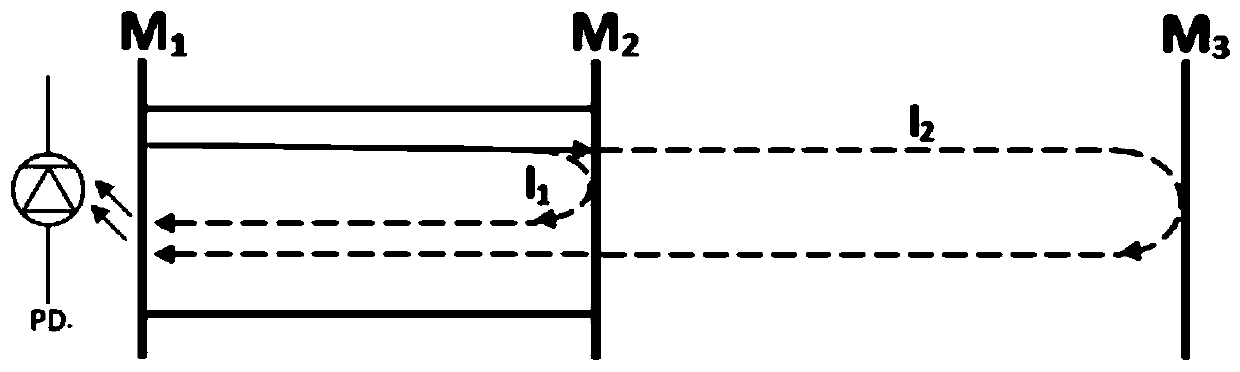
[0055] Step 4: Use the laser self-mixing interference device to measure the vibration of the non-destructive bearing. The three-mirror cavity model equivalent to the bearing housing and the laser self-mixing interference device is as follows: figure 2 Shown, M 1 , M 2 are the two end faces of the laser in the laser self-mixing interference device, M 3 is the side of the housi...


PUM


Abstract

The invention relates to a bearing fault detection device. The device comprises a workbench, a direct-current gear motor device, a bearing seat, a laser self-mixing interference device, a data collection and analysis device and a computer, wherein the direct-current gear motor device, the bearing seat and the laser self-mixing interference device are all arranged on the workbench, a to-be-detectedbearing is installed on the bearing seat, the direct-current gear motor device is connected with the bearing, the laser self-mixing interference device is arranged on the side face of the bearing seat and is connected with the data collection and analysis device, and the data collection and analysis device is connected with the computer. The bearing fault detection device has the advantages of being capable of performing non-contact measurement, easy to operate, high in interference resistance, high in sensitivity, high in measurement precision, loose in application condition, low in cost andthe like.

Description

technical field [0001] The invention relates to the technical field of bearing fault diagnosis, in particular to a bearing fault detection device and detection method. Background technique [0002] Bearings are an important part of contemporary machinery and equipment, and are widely used and demanding accessories and basic parts in the machinery industry. They are widely used in various fields of national economy and national defense. Because bearings play a supporting role in the rotating shafts or movable parts of various machines, they are also called "mechanical joints". Its main function is to support the mechanical rotating body, reduce the friction coefficient during its movement, and ensure its rotation accuracy. [0003] Whether the bearing runs normally or not has a great influence on the reliability, precision and life of the whole machine. According to relevant statistics, nearly 30% of the failure rate of rotating machinery is caused by the failure of rolling...

Claims


Application Information

Patent Timeline
Patent Type & Authority Applications(China)
IPC IPC(8): G01M13/045
CPCG01M13/045
Inventor 黄贞李栋宇王小卉李美琪
Owner LINGNAN NORMAL UNIV
Why Eureka
Try Eureka