Supercharge Your Innovation With Domain-Expert AI Agents!

Chimney tail gas sampling tube and using method thereof

A technology for sampling pipes and exhaust gas, which is applied in the direction of sampling, sampling devices, measuring devices, etc. It can solve the problems of different caliber positions and chimney height positions, and achieve the effect of reducing shaking and preventing collisions

Inactive Publication Date: 2019-10-18
广州市环境监测中心站
View PDF7 Cites 0 Cited by
  • Summary
  • Abstract
  • Description
  • Claims
  • Application Information

AI Technical Summary

Problems solved by technology

Moreover, many chimneys have different heights and calibers, which have high requirements for the adjustability of the sampling pipe.

Method used


Image

  • Chimney tail gas sampling tube and using method thereof
  • Chimney tail gas sampling tube and using method thereof
  • Chimney tail gas sampling tube and using method thereof

Examples


Embodiment

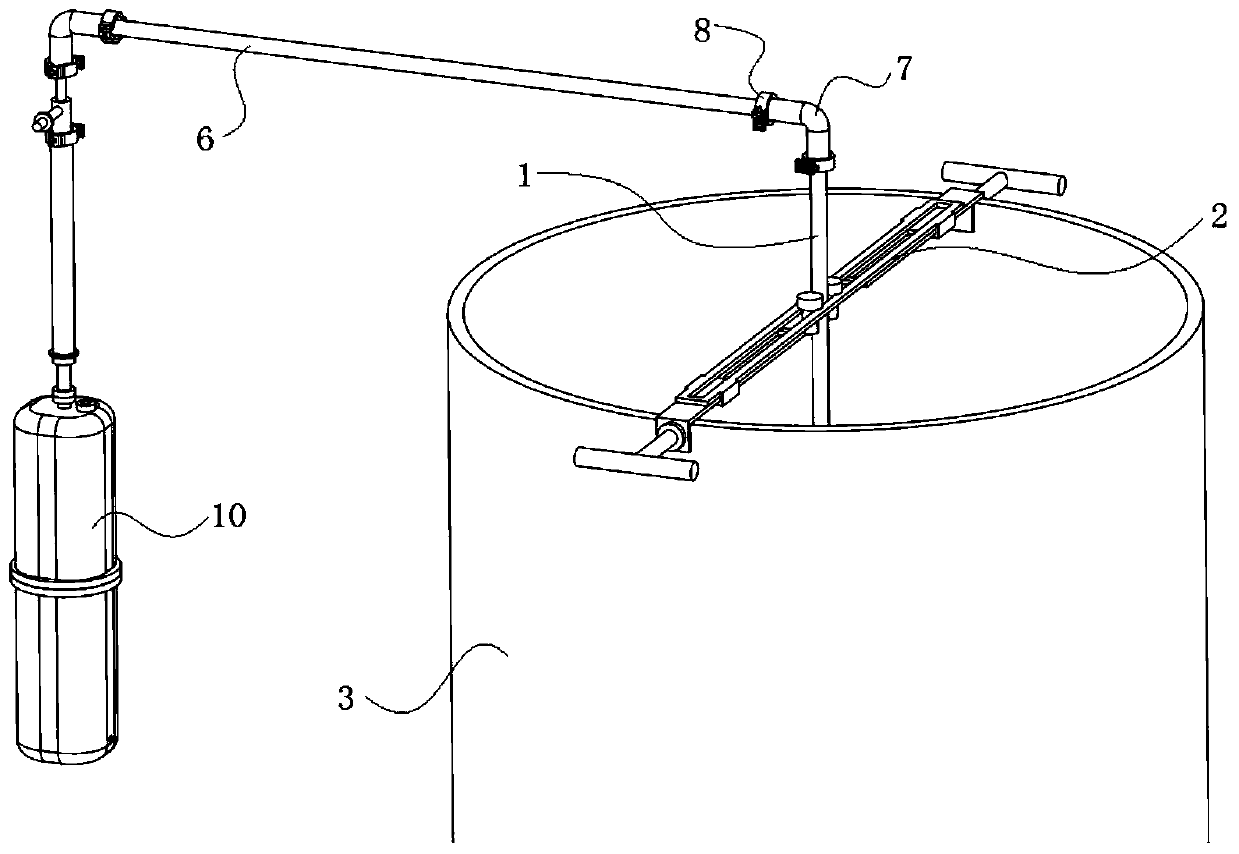
[0034] like Figure 1-2 As shown, this embodiment provides a chimney tail gas sampling pipe, which includes a collection pipe 1 and a fixing mechanism 2. The collection pipe 1 is vertically fixed to the chimney discharge port 3 through the fixing mechanism 2 to collect chimney tail gas.

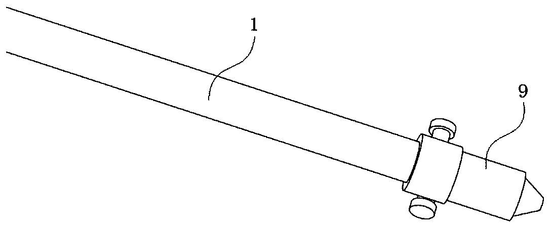
[0035] Wherein, the collection pipe 1 is a bendable copper pipe, and the copper collection pipe 1 can be bent into a corresponding shape according to the radian of the chimney pipe on site, so that it can be smoothly inserted into the chimney. At the same time, a sampling nozzle 9 is provided at the collection end of the collection pipe 1, and the sampling nozzle 9 is threadedly connected with the collection pipe 1. By replacing the sampling nozzle 9 with a different size and matching with a reasonable sampling flow rate, the constant velocity sampling of the flue gas can be realized, such as image 3 shown.

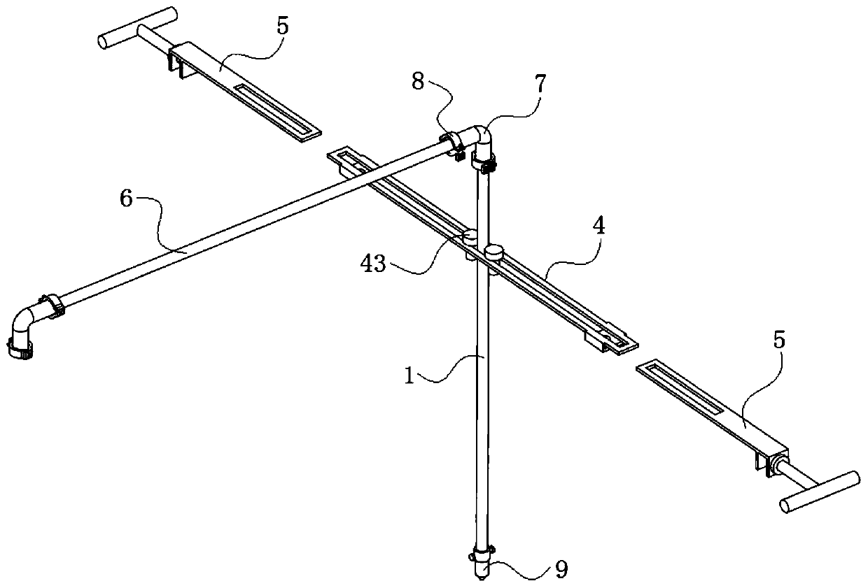
[0036] Further, the fixing mechanism 2 includes a fixing plate 4 and a fixing clip...

Embodiment 2

[0052] like Figure 8 As shown, this embodiment also provides a chimney tail gas sampling pipe, the structural principle is the same as that of embodiment 1, the difference is that this embodiment is used in the case where the diameter of the chimney discharge port 3 is small, and the fixing mechanism 2 does not include Fixed plate 4.

[0053] The fixing mechanism 2 of this embodiment is a fixing clip 4, including two side fixing clips 4 that are linearly symmetrical. The collection tube 1 passes through the overlapping first clamping section 511, is clamped by the first clamping section 511, and can adjust its position back and forth along the first clamping section 511. After the specific position of the collection tube 1 is determined, in its Tighten the threaded parts 43 on both sides to prevent the collection tube 1 from moving. In addition, if the fixing strength is sufficient, the fixing clip 5 on one side can also be used alone for clamping and fixing.


PUM


Abstract

The invention relates to the technical field of gas detection tools, in particular to a chimney tail gas sampling tube and a using method thereof. The chimney tail gas sampling tube comprises a collecting tube and a fixing mechanism, and the collecting tube is vertically fixed to a chimney discharging opening through the fixing mechanism for collecting chimney tail gas; the fixing mechanism is a fixing clamp, and the fixing clamp is fixed to the chimney discharging opening in a clamped mode; and a first clamping section is hollowed out in the middle of the fixing clamp, the collecting tube penetrates through the first clamping section and is clamped by the first clamping section, and the position of the collecting tube can be adjusted back and forth along the first clamping section. In addition, the collecting tube further comprises a plurality of extension tubes and a plurality of bends, the extension tubes or the bends are connected to the non-collecting end of the collecting tube for prolonging the collecting length or changing the collecting direction; and the connecting orders of the extension tubes and the bends can be mutually replaced. Meanwhile, the fixing mechanism further comprises a fixing plate used for expanding the fixing range, the fixing plate can be used under the situation that the diameter of the chimney discharging opening is large, and the sampling position of the sampling tube on the chimney section is precisely controlled.

Description

technical field [0001] The invention relates to the technical field of gas detection tools, in particular to a chimney tail gas sampling pipe and a method for using the same. Background technique [0002] Commercial chimney sampling devices on the market can only be operated on chimneys with sampling holes. Due to the special structure of ship chimneys, the exhaust gas emission concentration is high and the temperature is high. Opening sampling holes may cause toxic gases to leak into the cabin, endangering personal safety. Therefore, there are no sampling holes in the ship's chimneys. At present, some monitoring work mainly conducts monitoring and sampling by extending directly into the sampling pipe from the exhaust port of the ship's chimney. However, if the sampling pipe is directly inserted into the exhaust port of the chimney for collection, the impact of the airflow will easily cause the sampling pipe itself to shake continuously, and even cause the sampling pipe to ...

Claims


Application Information

Patent Timeline
IPC IPC(8): G01N1/22G01N1/26
CPCG01N1/2258G01N1/26G01N2001/2261
Inventor 陈鸿展何俊杰陈俊文
Owner 广州市环境监测中心站
Features
  • R&D
  • Intellectual Property
  • Life Sciences
  • Materials
  • Tech Scout
  • Unparalleled Data Quality
  • Higher Quality Content
  • 60% Fewer Hallucinations
Learn More