Heat management system of vehicle power battery

A technology of thermal management system and power battery, applied in the field of thermal management system, can solve the problems of long development cycle, high component cost, hindering the widespread development of new energy vehicles, etc., achieve easy modularization and standardization, and solve the problem of sharp drop in output, The effect of simplifying bicycle development

Active Publication Date: 2019-10-22
CHONGQING CHANGAN AUTOMOBILE CO LTD
View PDF14 Cites 1 Cited by
  • Summary
  • Abstract
  • Description
  • Claims
  • Application Information

AI Technical Summary

Problems solved by technology

The existing technology usually uses a first-stage water-cooled heat exchanger to indirectly cool the battery, which has low heat transfer efficiency, difficult control, large heat loss along the process, high component costs, and long development cycle
In fact, a thermal management system must be developed for a car model, making it difficult to achieve modularization and standardization of system development
[0006] Furthermore, the heat pump system that also takes into account the heating of the battery makes the thermal management system more complex. Taking the above-mentioned BMW as an example, the heat pump system adds 36 components and increases the weight by about 7KG
[0007] The above situation makes it very difficult for new energy vehicles to be practical in winter in the vast alpine regions and general areas. It has formed a technical bottleneck worldwide and hindered the extensive development of new energy vehicles.
[0008] In view of the above situation, a separate cooling design for the power battery has emerged, but its function is limited to the realization of the cooling function

Method used


Image

  • Heat management system of vehicle power battery
  • Heat management system of vehicle power battery
  • Heat management system of vehicle power battery

Examples


Embodiment Construction

[0030] Below in conjunction with accompanying drawing, the present invention will be further described, and it should be noted that the embodiments described here are only used for illustration, and do not limit the present invention:

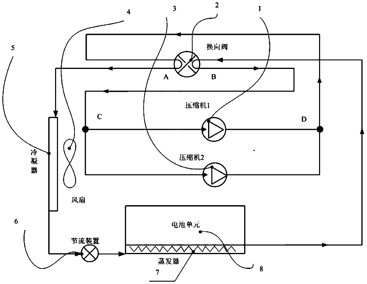
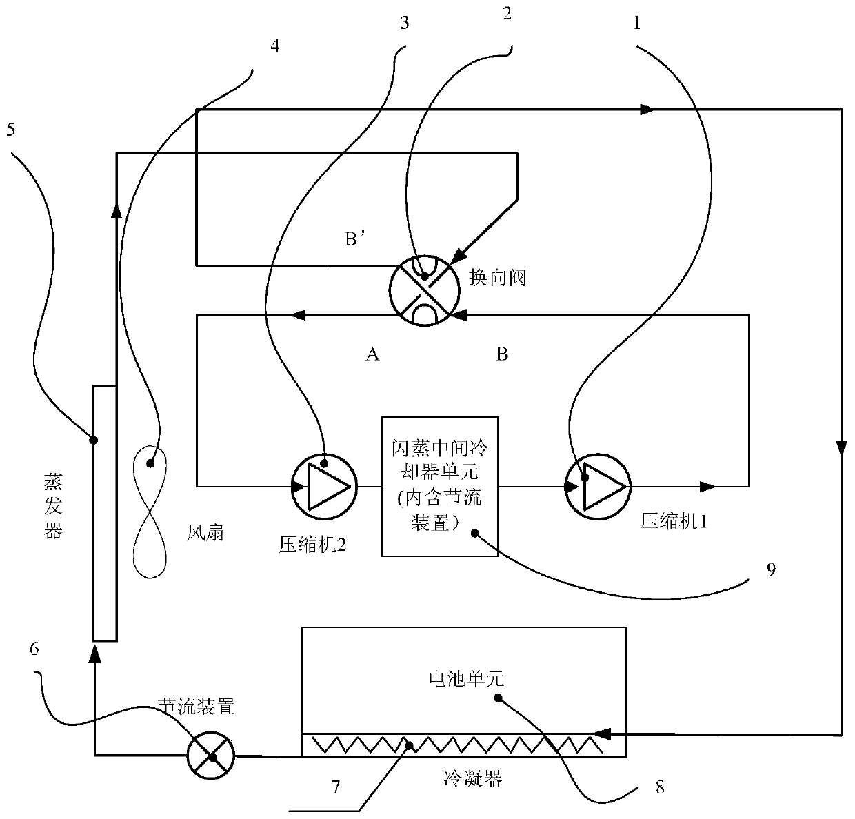
[0031] see figure 1, is the refrigeration working principle of the present invention, and the system includes a compressor unit (including the first compressor 1 and the second compressor 3), a four-way reversing valve 2, a condenser fan 4, and an external heat exchanger 5 (in In different states, they act as condensers or evaporators respectively), throttling device 6 (expansion valve or its type throttling mode), battery heat exchanger 7 (in different states, act as evaporators or condensers respectively function), the battery unit 8 (cooling object), and other related components such as the connecting pipelines of each section and the switching valves that control the on-off of each pipeline.

[0032] When the battery is in the cooled stat...


PUM


Abstract

The invention relates to a heat management system of a vehicle power battery. The heat management system comprises a compressor set, a four-way reversing valve, a condenser fan, an external heat exchanger, a battery heat exchanger and a battery cell unit, wherein the external heat exchanger and the battery heat exchanger are connected through a pipeline and are connected with the compressor set and a flash evaporation intermediate cooling unit through the four-way reversing valve, the compressor set comprises two compressors, the flash evaporation intermediate cooling unit is connected betweenthe two compressors; the two compressors form a series or parallel structure by controlling the on-off of each switching valve on the connecting pipeline, under the refrigeration working condition, the parallel mode is adopted, the cooling effect of the battery is enhanced, under the working condition of the heat pump, a series operation mode is adopted, the double-stage compression is achieved,so that the heating efficiency of the battery is remarkably improved under the low-temperature condition. The system has the characteristic that the battery is subjected to heat management independently of the vehicle, the technical bottleneck of rapid reduction of output of the power battery under the low-temperature condition in winter is solved, and meanwhile, the system development is easy tomodularize and standardize.

Description

technical field [0001] The invention belongs to the field of new energy vehicles, including BEV (pure electric vehicle), PHEV (plug-in hybrid electric vehicle) and HEV (hybrid electric vehicle), and specifically relates to a thermal management system for cooling and heating vehicle-mounted power batteries. Background technique [0002] The vehicle thermal management system of a traditional vehicle usually includes an engine cooling system and an air-conditioning system for the occupants in the car. The air-conditioning system cools the cabin through a set of vapor compression refrigeration system in summer and hot days, and uses engine exhaust in winter or cold weather. The heat generated warms the cabin. [0003] Due to the needs of the world's environmental protection and the tight supply of crude oil, new energy vehicles have emerged in the world, including pure electric drive BEV and hybrid drive types HEV (hybrid electric drive) and PHEV (plug-in hybrid electric drive)....

Claims


Application Information

Patent Timeline
Patent Type & Authority Applications(China)
IPC IPC(8): B60L58/26B60L58/27
CPCB60L58/26B60L58/27Y02T10/70
Inventor 游典翟昱民
Owner CHONGQING CHANGAN AUTOMOBILE CO LTD
Why Eureka
Try Eureka