Anti-agglomerating screw conveyer

A screw conveyor and screw conveyor shaft technology, which is applied in the field of anti-caking screw conveyors, can solve problems such as difficult cleaning and easy caking, and achieve high production efficiency, avoid fatigue damage, and stable equipment operation

Pending Publication Date: 2019-10-22
GUANGXI LIYUANBAO SCI & TECH
View PDF0 Cites 1 Cited by
  • Summary
  • Abstract
  • Description
  • Claims
  • Application Information

AI Technical Summary

Problems solved by technology

[0010] The purpose of the present invention is to solve the technical and technological problems that the existing screw conveyor is prone to material clogging and difficult to clean up after the material is clogged, and to provide an anti-caking screw conveyor

Method used


Image

  • Anti-agglomerating screw conveyer
  • Anti-agglomerating screw conveyer
  • Anti-agglomerating screw conveyer

Examples


Embodiment 1

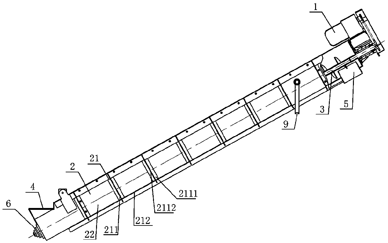
[0035] like figure 1 As shown, the anti-caking screw conveyor of the first embodiment of the present invention is mainly composed of a gear motor 1, a conveying cylinder 2, a screw conveying shaft 3, a feeding port 4, a discharging port 5, a screw bearing seat 6 and a mounting bracket 9. , wherein the reduction motor 1 is connected and installed at one end of the conveying cylinder 2, the screw conveying shaft 3 is connected and installed in the conveying cylinder 2 through the screw bearing seats 6 installed at both ends of the conveying cylinder 2, and the screw One end of the conveying shaft 3 is connected with the deceleration motor 1 for transmission, the feeding port 4 of the screw conveyor is arranged above the conveying cylinder 2, and the discharging port 5 is arranged on the conveying cylinder. 2 below.

[0036] The conveying cylinder 2 is formed by connecting and combining a U-shaped hollow frame 21 and a soft material plate 22; the soft material plate 22 is instal...

Embodiment 2

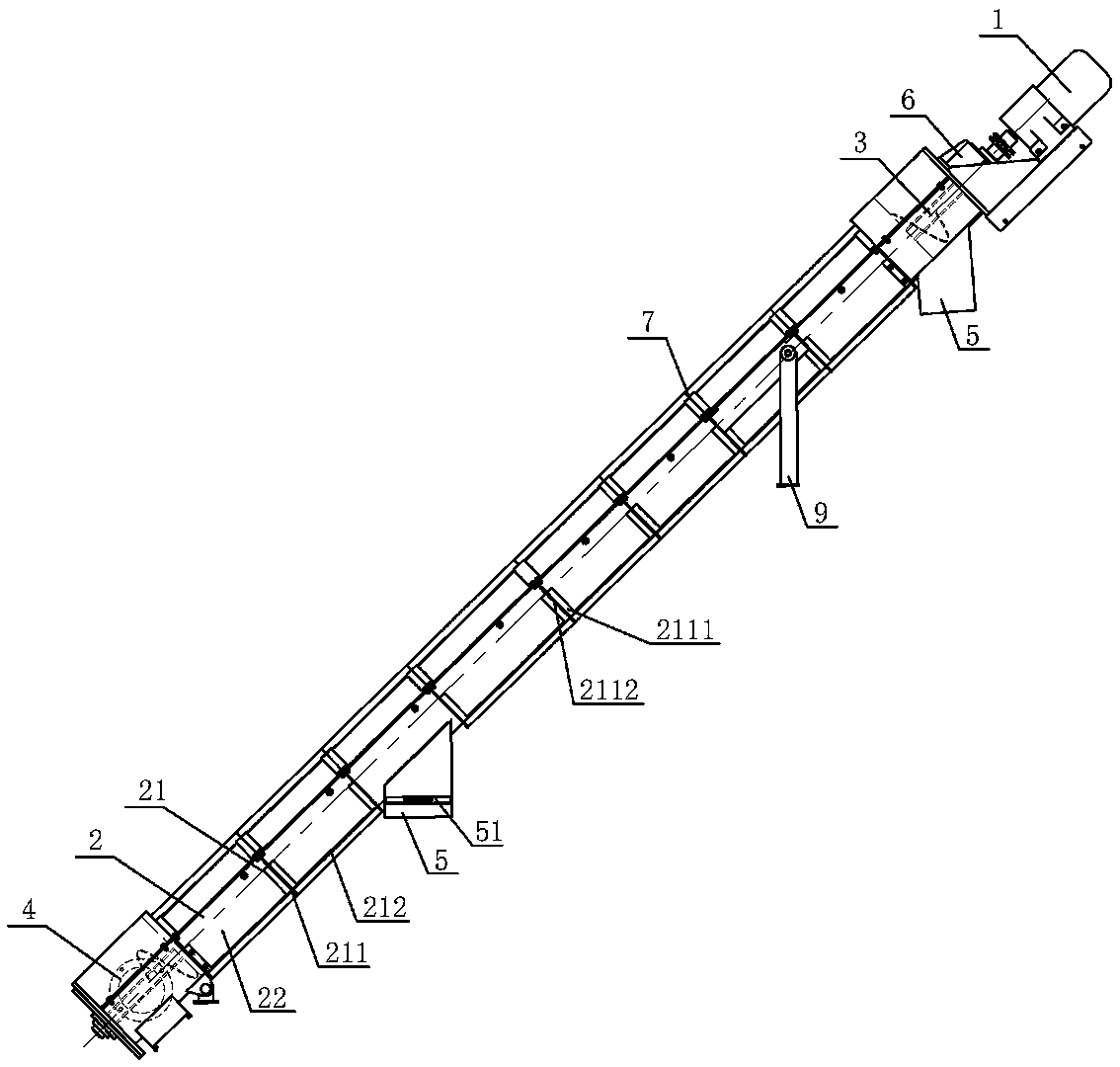
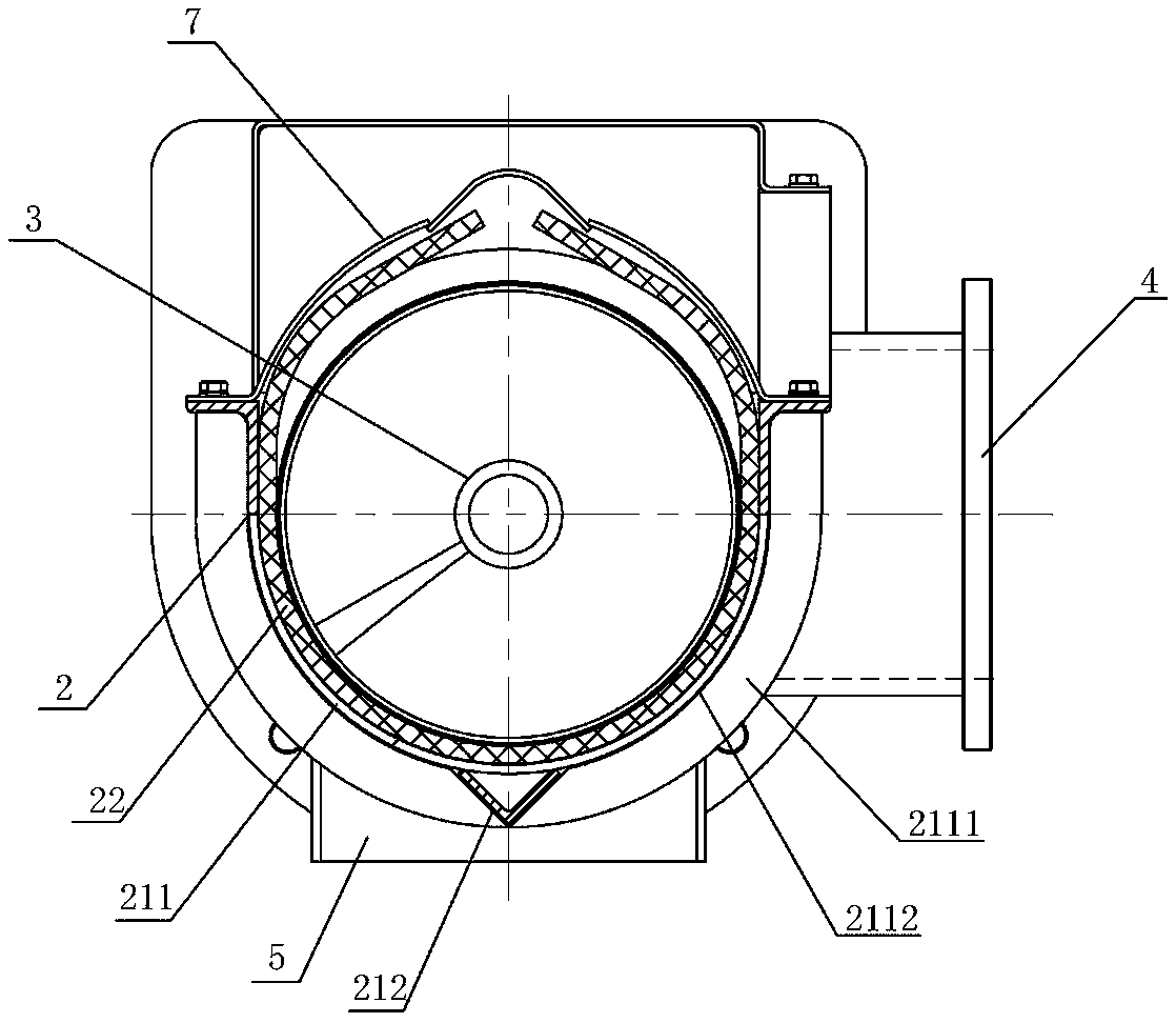
[0040] like figure 2 , image 3 As shown, the anti-caking screw conveyor of the second embodiment of the present invention is similar to that of the first embodiment, and the difference is only that:

[0041] The conveying cylinder 2 is formed by connecting a semi-circular hollow frame 21 and a soft material plate 22; the soft material plate 22 is connected and installed on the inner side of the semi-circular hollow frame 21 by means of countersunk screws. The cylinder body upper buckle 7 is provided; the cylinder body upper buckle 7 is arc-shaped, and is installed on the radial frame 212 of the hollow frame 21 above the conveying cylinder body 2 by screw connection, for withholding the soft material plate 22 is an oval-shaped soft conveying cylinder formed by bending inward; in order to facilitate disassembly and assembly, the upper buckle 7 of the cylinder is divided into a plurality of combined installations; the semicircular hollow frame 21 is composed of several axially a...

Embodiment 3

[0044] like Figure 4 , Figure 5 As shown, the anti-caking screw conveyor of the third embodiment of the present invention is similar to that of the first embodiment, and the difference is only that:

[0045] In order to make the screw conveyor realize the material distribution function of one-point feeding and multi-point discharging, one feeding port 4 is provided above the middle of the conveying cylinder 2, and four discharging ports 5 are provided. Two sides of the feeding port 4 are provided on each side, and the discharging port door 51 is installed under the discharging port 5 near both sides of the feeding port 4, and at the same time, the discharge port door 51 is installed for the mixed materials from the The feeding port 4 enters and discharges to the discharging ports 5 on both sides at the same time. The screw conveying shaft 3 is a combined shaft extending from the middle to both ends, and the directions of the screw blades on both sides are opposite.

[0046...


PUM


Abstract

The invention provides an anti-agglomerating screw conveyer. The anti-agglomerating screw conveyer comprises a speed reducing motor, a conveying cylinder, a screw conveying shaft, a feeding port, a discharging port and a screw bearing pedestal. On the basis of an existing screw conveyer, a semi-circular or circular-arc-shaped or U-shaped hollow skeleton is adopted to be connected and combined witha soft material plate, a semi-circular or oval or U-shaped soft conveying cylinder capable of achieving elastic bending is formed, the defects that the equipment load is large, halting is prone to occurring, equipment wear is fast, and the working life is short due to the fact that for an existing screw conveyer, agglomerating is prone to occurring, or cleaning is difficult after agglomerating occurs are overcome, the structure is skillful, the equipment manufacturing and maintaining cost is low, running is stable, no noise is generated, the working condition is stable, and the working efficiency is high.

Description

technical field [0001] The invention belongs to the field of conveying equipment, in particular to an anti-caking screw conveyor. Background technique [0002] In the industrial production process of organic fertilizer, feed and other industries, conveying equipment is one of the indispensable equipment. Due to its small size and small leakage during conveying, screw conveyors are also widely used in production lines. [0003] Commonly used screw conveyors are mainly composed of driving gear motor, screw conveying shaft, conveying cylinder, feeding port and discharging port, and the conveying cylinder is generally composed of steel pipe or steel U-shaped groove, and some of them are made of PVC and so on. Made of molecular material tubes. The screw conveyor designed and manufactured in this way can basically convey materials with low moisture content, low viscosity and good fluidity, and in the case of a small elevation angle of the conveyor, it can basically achieve smooth...

Claims


Application Information

Patent Timeline
Patent Type & Authority Applications(China)
IPC IPC(8): B65G33/10B65G33/24
CPCB65G33/10B65G33/24B65G2207/32B65G2207/20B65G2207/26
Inventor 邓秀泉韦江泉
Owner GUANGXI LIYUANBAO SCI & TECH
Why Eureka
Try Eureka