Protected glass cutting machine

A cutting machine and cutting technology, used in glass cutting devices, glass manufacturing equipment, metal processing and other directions, can solve the problems of glass tube damage, uneven cutting cuts, low cutting speed, etc., and improve the separation speed. , improve stability and improve efficiency

Active Publication Date: 2019-10-22
蚌埠市鑫诚玻璃机械有限公司
View PDF4 Cites 9 Cited by
  • Summary
  • Abstract
  • Description
  • Claims
  • Application Information

AI Technical Summary

Problems solved by technology

[0002] In the traditional glass tube cutting device, the position of the rotatable cutting knife is fixed, and the rotation of the glass tube cuts the glass tube under the action of the cutting knife, and during the cutting process, only the input side of the glass tube is set If there is a fastening structure, the output side of the cutting position is easily shifted by the cutting force, resulting in uneven layers of the cutting opening, and the cutting speed is low. Secondly, during the cutting work, due to the glass tube and the cutting Keep the cutting knife in contact state, when the glass tube is input, the cutting knife is easy to scratch the surface of the glass tube, causing damage to the glass tube

Method used


Image

  • Protected glass cutting machine
  • Protected glass cutting machine
  • Protected glass cutting machine

Examples


Embodiment Construction

[0022] Combine below Figure 1-Figure 8 The present invention is described in detail, and for convenience of description, the orientations mentioned below are now stipulated as follows: figure 1 The up, down, left, right, front and back directions of the projection relationship itself are consistent.

[0023] The present invention relates to a protective glass cutting machine, which is mainly used for cutting glass tubes. The present invention will be further described below in conjunction with the accompanying drawings of the present invention:

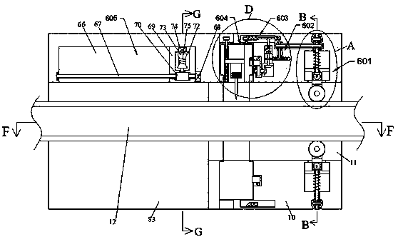
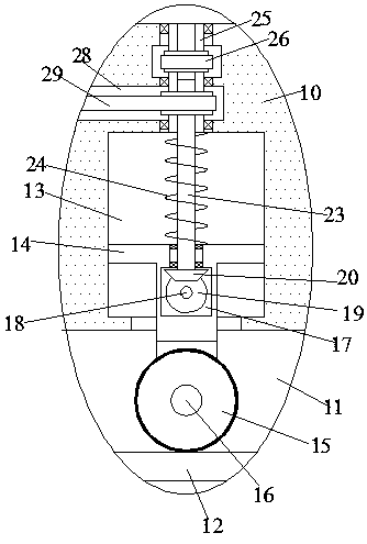
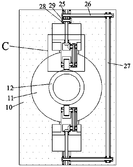
[0024]A protective glass cutting machine according to the present invention includes a cutting main body 10, a cutting chamber 11 is arranged inside the cutting main body 10, a conveying device 601 is arranged inside the cutting chamber 11, and the conveying device 601 is arranged inside the cutting chamber 11. The device 601 includes a vertically symmetrical conveying wheel 15. The opposite rotation of the conveying wheel 15 can dr...


PUM


Abstract

The invention discloses a protected glass cutting machine. The protected glass cutting machine comprises a cutting main body; a cutting cavity is formed in the cutting main body; a conveying device isarranged in the cutting cavity; the conveying device comprises conveying rotary wheels which are symmetrical up and down; the conveying rotary wheels rotate relatively to drive a glass pipe to move leftwards for cutting; a heated cutting knife rotates along the glass pipe to rapidly cut the glass pipe, and an output device and a conveying device are arranged on the left side and the right side ofthe glass pipe cutting position correspondingly, so that steadiness of the glass pipe is guaranteed and the stability of glass pipe cutting is improved; and when the glass pipe is input leftwards, the cutting knife is not abutted against the glass pipe through a telescopic device, the outer surface of the glass pipe is prevented from being scratched by the cutting knife, and the separation speedof the cutting position of the cut glass pipe can be increased through a vibrating device, so that the efficiency of the whole cutting work is improved.

Description

technical field [0001] The invention relates to the technical field of glass cutting, in particular to a protective glass cutting machine. Background technique [0002] In the traditional glass tube cutting device, the position of the rotatable cutting knife is fixed, and the rotation of the glass tube cuts the glass tube under the action of the cutting knife, and during the cutting process, only the input side of the glass tube is set If there is a fastening structure, the output side of the cutting position is easily shifted by the cutting force, resulting in uneven layers of the cutting opening, and the cutting speed is low. Secondly, during the cutting work, due to the glass tube and the cutting If the cutter remains in contact with each other, then when the glass tube is input, the cutter will easily scratch the surface of the glass tube, causing damage to the glass tube. The present invention illustrates a device capable of solving the above-mentioned problems. Cont...

Claims


Application Information

Patent Timeline
Patent Type & Authority Applications(China)
IPC IPC(8): C03B33/06
CPCC03B33/06B26D3/16B26D7/10C03B33/105
Inventor 姚建华
Owner 蚌埠市鑫诚玻璃机械有限公司
Why Eureka
Try Eureka