Desorption flow fault detecting device and method for vehicle evaporative emission system and vehicle

A technology of desorption flow rate and evaporative emission, which is applied in the field of vehicle emission and can solve the problems of low accuracy

Active Publication Date: 2019-10-22
CHINA FIRST AUTOMOBILE
View PDF9 Cites 5 Cited by
  • Summary
  • Abstract
  • Description
  • Claims
  • Application Information

AI Technical Summary

Problems solved by technology

[0005] The invention provides a vehicle evaporative emission system desorption flow fault detection device, method and vehicle to solve the technical problem of low accuracy of the current evaporative emission system desorption flow fault detection method

Method used


Image

  • Desorption flow fault detecting device and method for vehicle evaporative emission system and vehicle
  • Desorption flow fault detecting device and method for vehicle evaporative emission system and vehicle
  • Desorption flow fault detecting device and method for vehicle evaporative emission system and vehicle

Examples


Embodiment Construction

[0026] The present invention will be further described in detail below in conjunction with the accompanying drawings and embodiments. It should be understood that the specific embodiments described here are only used to explain the present invention, but not to limit the present invention. In addition, it should be noted that, for the convenience of description, only some structures related to the present invention are shown in the drawings but not all structures.

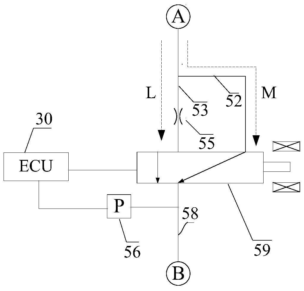
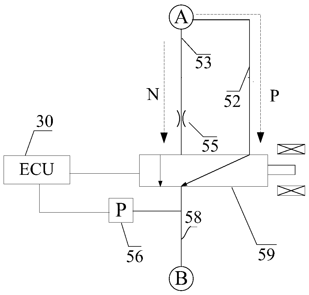
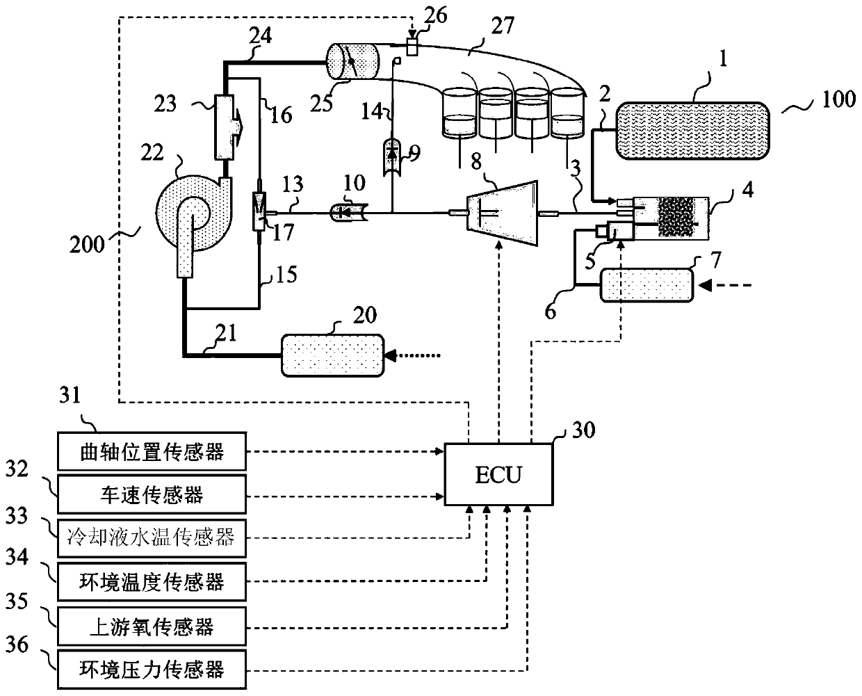
[0027] figure 1 It is a schematic structural diagram of an embodiment of a device for detecting a desorption flow failure of a vehicle evaporative emission system provided by the present invention. Figure 3A for figure 1 A schematic diagram of an installation mode of the vehicle evaporative emission system desorption flow fault detection device in the illustrated embodiment in the vehicle evaporative emission system. Figure 3B for figure 1 A schematic diagram of another installation method of the vehicle evap...


PUM


Abstract

The invention discloses a desorption flow fault detecting device and method for a vehicle evaporative emission system and a vehicle. The device comprises an ECU, a pressure sensor, a flow restrictionorifice, a switching valve, a first vacuum pipeline, a second vacuum pipeline and a third vacuum pipeline. The diameter of the flow restriction orifice is smaller than an inner diameter of the secondvacuum pipeline, one end of the first vacuum pipeline is in communication with the atmosphere, the other end of the first vacuum pipeline is connected to a first end of the switching valve, the flow restriction orifice is disposed on the first vacuum pipeline, one end of the second vacuum pipeline is in communication with the atmosphere, the other end of the second vacuum pipeline is connected toa second end of the switching valve, one end of the third vacuum pipeline is connected to a third end of the switching valve, and the other end of the third vacuum pipeline communicates with an atmospheric communication port of an activated carbon canister of the vehicle or is connected to an air inlet of a desorption control valve of the vehicle, and the pressure sensor is set on the third vacuumpipeline. According to the device, the accuracy of detecting a desorption flow fault of the vehicle evaporative emission system is improved.

Description

technical field [0001] The embodiments of the present invention relate to the technical field of vehicle emission, and in particular to a vehicle evaporative emission system desorption flow fault detection device, method and vehicle. Background technique [0002] Currently, vehicles powered by internal combustion engines are still the mainstream of the automotive market. Vehicles powered by internal combustion engines are usually supplied with fuel by a fuel tank system. According to the current requirements of my country's light-duty vehicle emission regulations, the fuel tank system needs to include an evaporative emission system to recover the fuel vapor in the fuel tank system and prevent the fuel vapor from being discharged into the atmosphere to pollute the environment. A typical evaporative emission system includes an activated carbon canister for absorbing fuel vapor generated in the fuel tank, and a desorption control valve in the middle of the pipeline connecting ...

Claims


Application Information

Patent Timeline
Patent Type & Authority Applications(China)
IPC IPC(8): G01M17/007
CPCG01M17/007
Inventor 刘廷伟孙鹏远孙超张波邹铁苍贺成刘笑飞
Owner CHINA FIRST AUTOMOBILE
Why Eureka
Try Eureka