Pneumatically protected anti-impurity groundwater sampling and detecting device

A technology of pneumatic protection and detection device, applied in sampling devices, measuring devices, sampling and other directions, can solve the problems of inaccurate data collection and blockage of water samples, and achieve the effect of easy maintenance and supplementation, convenient use, and avoidance of sludge and impurities.

Inactive Publication Date: 2019-10-22
安娜
View PDF0 Cites 5 Cited by
  • Summary
  • Abstract
  • Description
  • Claims
  • Application Information

AI Technical Summary

Benefits of technology

This technology helps regulate the movement of an object's position within its housing while collecting samples from different locations on-the-go. By controlling how much pressure (pressure) needs to occur before the water starts draining back up inside the device, this allows accurate measurements over longer periods without having to stop working altogether. Additionally, there are benefits such as prevention of clogging caused by debris particles entering pipelines due to their size being too small compared to larger objects like rocks). Overall, these technical features help make sampling more efficient and effective across various applications where water quality monitoring becomes necessary.

Problems solved by technology

This patented technical problem addressed by this patents relates to improving accuracy during sampling for analyzing soil-based waters from various sources like wellbores drilled through oil fields containing high levels of dissolved solids (such as calcium) found near populated areas where there may be heavy rain events affecting drinkable supplies used throughout life. Current methods involve extending an extra tool inside the collected water before analysis can take place but these tools often get stuck with sediment causing incorrect results.

Method used


Image

  • Pneumatically protected anti-impurity groundwater sampling and detecting device
  • Pneumatically protected anti-impurity groundwater sampling and detecting device
  • Pneumatically protected anti-impurity groundwater sampling and detecting device

Examples


Embodiment 1

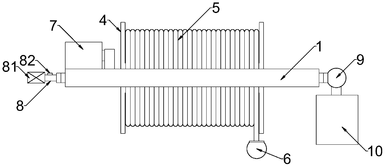
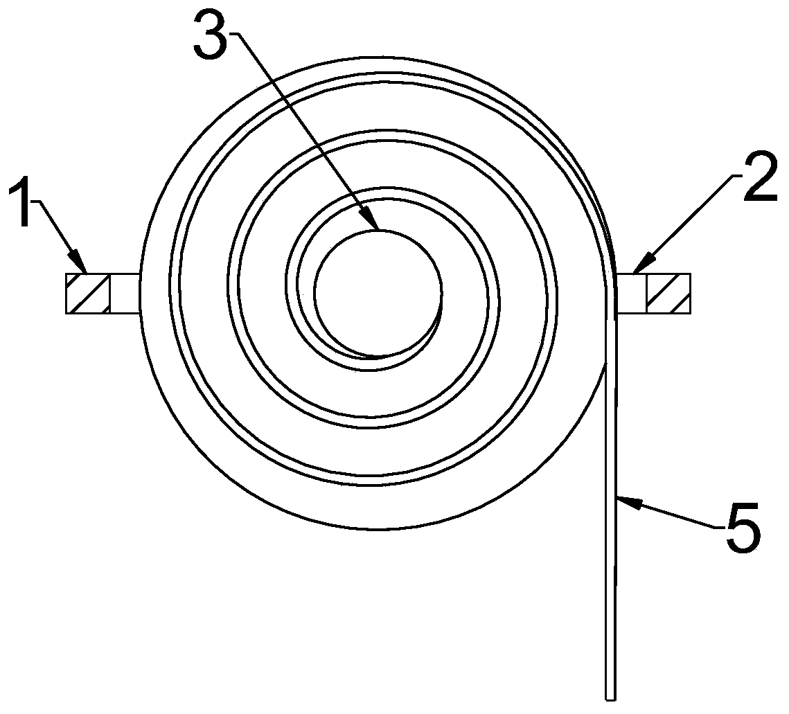
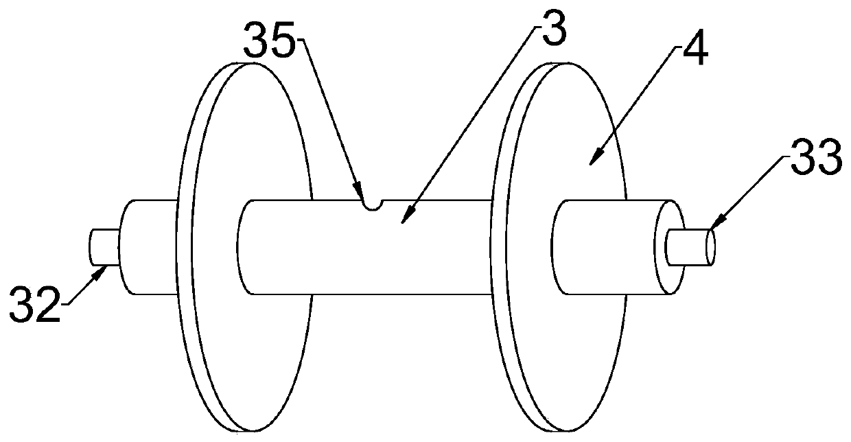
[0024] see Figure 1~4 , in an embodiment of the present invention, a pneumatically protected anti-miscellaneous groundwater sampling detection device includes a setting plate 1, a winding shaft 3, a water inlet hose 5, a water sampling head 6 and a detection structure 10, and the middle part of the setting plate 1 runs through the A placement hole 2 is provided, an air outlet pipe 32 and a liquid outlet pipe 33 are symmetrically connected at both ends of the winding shaft 3, a water inlet hose 5 is wound around the periphery of the winding shaft 3, and one end of the water inlet hose 5 is connected to the winding The bobbin 3 is connected, and the end of the water inlet hose 5 away from the bobbin 3 is connected with a water harvesting head 6, and the bobbin 3 is rotated through the air outlet pipe 32 and the liquid outlet pipe 33 that pass through the side wall of the placement hole 2 and are rotatably connected. The end of the air outlet pipe 32 is connected with an air inj...

Embodiment 2

[0031] see Figure 5, in the embodiment of the present invention, a pneumatically protected anti-miscellaneous groundwater sampling and detection device, on the basis of embodiment 1, the water sampling head 6 includes a backing plate 61 and multiple sets of side plates that are rotatably connected to the edge of the backing plate 61 62, the backing plate 61 is a circular metal sheet, and the periphery of the backing plate 61 is symmetrically hinged in a cross-shaped direction with four sets of side plates 62, and the middle part of the upper end of the side plate 62 is rotationally connected with the backing plate 61, and four sets The side plates 62 are movably pieced together to form a spherical structure, the inner wall of the side plate 62 is embedded with a sliding groove 63, and a sliding ball head 68 is slidably fitted in the sliding groove 63; the middle part of the backing plate 61 is provided with a connecting pipe 64, the lower end of the connecting pipe 64 extends...


PUM


Abstract

The invention discloses a pneumatically protected anti-impurity groundwater sampling and detecting device, which comprises a mounting plate, a bobbin, a water inlet hose, a water collecting head and adetecting structure, wherein a mounting hole passes through the central part of the mounting plate; an air outlet pipe and a liquid outlet pipe are symmetrically connected with the two ends of the bobbin the water inlet hose is wound around the bobbin; one end of the water inlet hose is in communication with the bobbin; the water inlet hose is in communication with the water collecting head at the end away from the bobbin; and the bobbin is rotated by the air outlet pipe and the liquid outlet pipe which pass through to the side wall of the mounting hole and are rotatably connected. The watercollecting head is opened or closed pneumatically during the sinking process of the water collecting head, thereby preventing the blockage of sludge impurities in the water from affecting the collection of a water sample and improving the collection precision. The water inlet hose is driven by a motor to be wound or released so as to control the lifting and lowering of the water collecting head, thereby contributing to the control of the depth of water collection to achieve water collection at any depth.

Description


Claims


Application Information

Patent Timeline
Owner 安娜
Why Eureka
Try Eureka