Frame for flat core cladding metal spraying
A core package and frame technology, which is applied in terminal application devices, capacitor manufacturing, electrical components, etc., can solve problems such as the inability to position the frame and the integrated structure, the inconvenient disassembly and replacement of the gold spray plate, and the uneven force on the flat core package. problems, to achieve the effect of improving convenience, improving gold spraying efficiency, and avoiding uneven force
- Summary
- Abstract
- Description
- Claims
- Application Information
AI Technical Summary
Problems solved by technology
Method used
Image

Examples
Embodiment 1
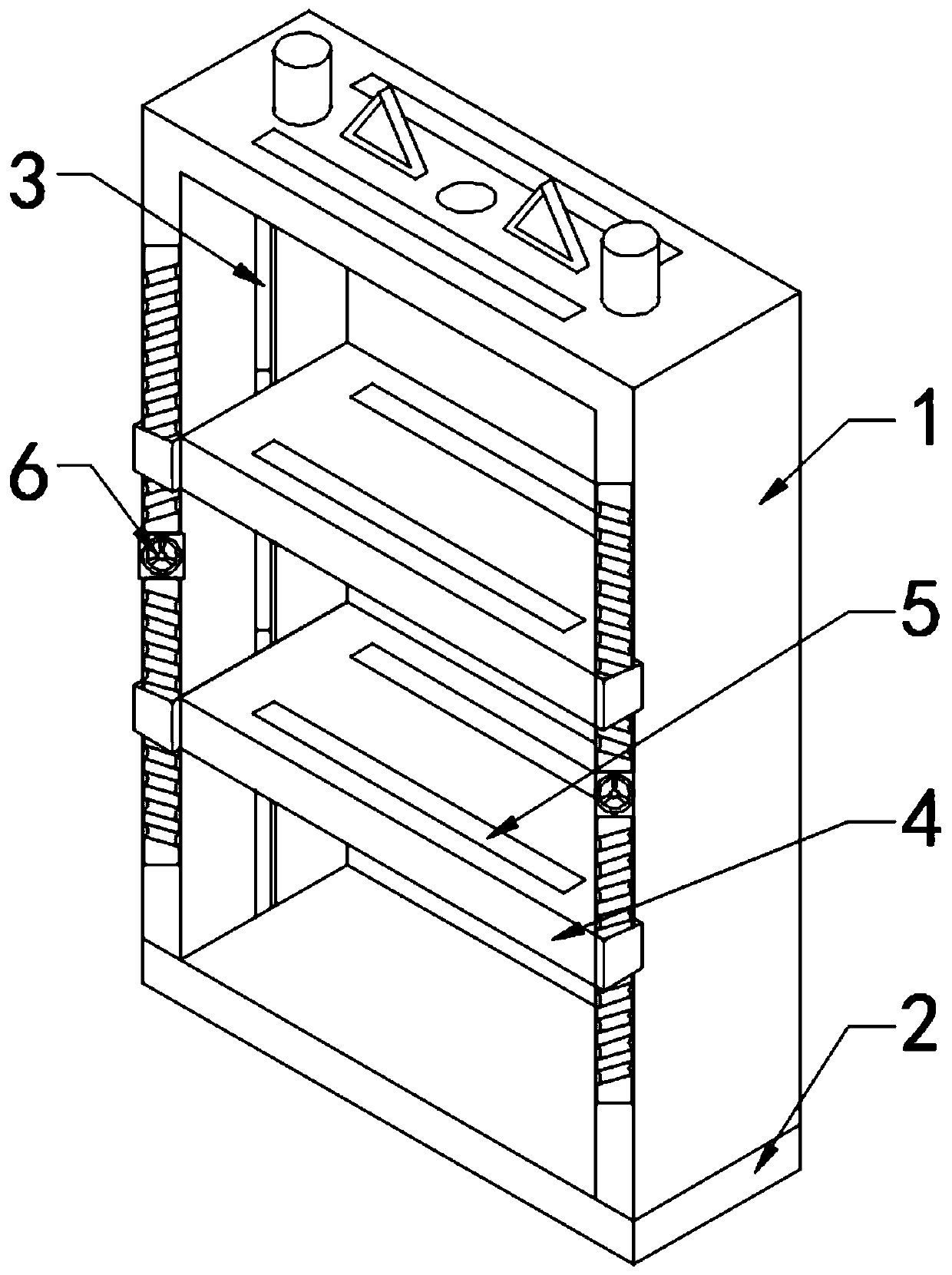
[0034] see Figure 1-5 , a frame for spraying gold on a flat core package, including a frame 1, a bottom plate 2 and a flat core package 7, the frame 1 is in an inverted U-shaped structure, and the two vertical ends of the frame 1 are symmetrically opened along the vertical axis. The card slot 3 and the setting of the card slot 3 are convenient for the up and down sliding of the two gold-sprayed plates 4. There are two gold-sprayed plates 4 slidingly connected between the two vertical ends of the frame tool 1 through the card slot 3, and the frame tool 1 The center positions of the two vertical ends of the front end face are equipped with a vertical leading screw 6, and two threaded rods with opposite thread directions are installed symmetrically on the upper and lower sides of the leading screw 6, so that when the leading screw 6 is adjusted, the two symmetrically arranged The gold-sprayed plate 4 can move both sides and the middle at the same time, which is convenient for th...
Embodiment 2
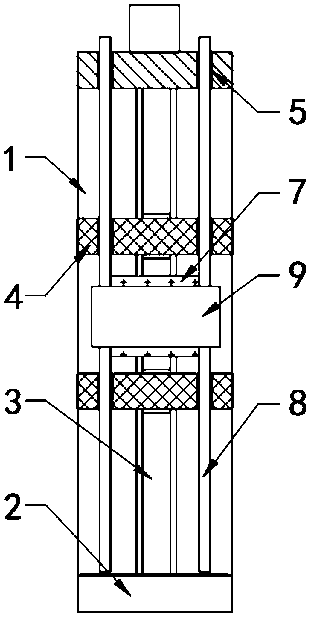
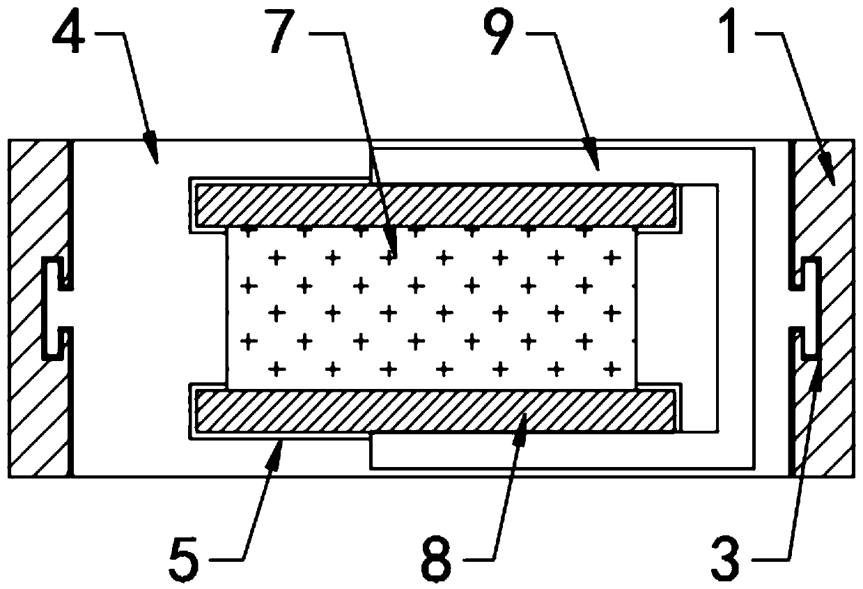
[0036] see Figure 1-4 , the inside of the two gold-sprayed plates 4 and the horizontal end of the frame 1 are correspondingly provided with two parallel slots 5, and the inside of the slot 5 is slidably connected with a thin plate 8 with a height higher than the frame 1, so that the thin plate 8 can be Restricted by the two gold-sprayed plates 4 and the horizontal end of the frame 1, it is also convenient to take out the thin plate 8, and a C-shaped clip with a height smaller than the thickness of the flat core package 7 is horizontally clamped between the two thin plates 8 9. Ensure that the C-shaped clip 9 does not affect the clamping of the two gold-sprayed plates 4 on the flat core package 7. The thin plate 8 is made of elastic material, so that the C-shaped clip 9 can stably fix the flat core package 7 between the two thin plates 8 The distance between the two thin plates 8 is equal to the width of the flat core package 7 .
[0037] Except for the above differences, the...
Embodiment 3
[0039] see Figure 4 , the two thin plates 8 take the horizontal axis of the frame 1 as the center line to open a visible hole 10 with a horizontal length greater than the length of the flat core package 7, which is convenient for the left and right adjustment of the flat core package 7. The position of the thin plate 8 near the visible hole 10 is engraved with The dimensions symmetrical to the vertical axis of the frame 1 enable the flat core package 7 to quickly find the horizontal center position.
[0040] Except for the above differences, the technical solution in this embodiment is consistent with the second embodiment.
PUM
 Abstract
Description
Claims
Application Information
 - R&D Engineer
- R&D Manager
- IP Professional
- Industry Leading Data Capabilities
- Powerful AI technology
- Patent DNA Extraction
Browse by: Latest US Patents, China's latest patents, Technical Efficacy Thesaurus, Application Domain, Technology Topic.
© 2024 PatSnap. All rights reserved.Legal|Privacy policy|Modern Slavery Act Transparency Statement|Sitemap