

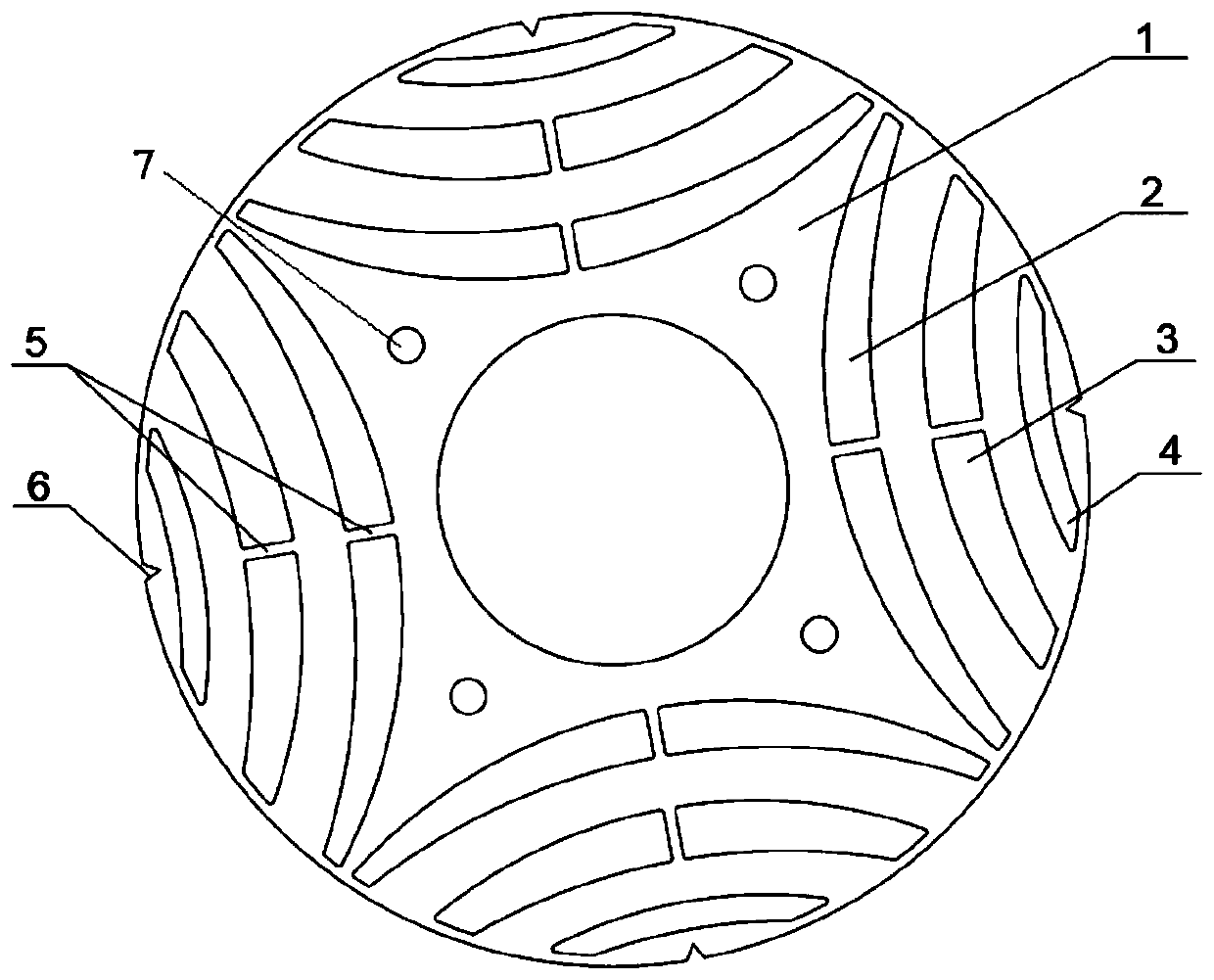
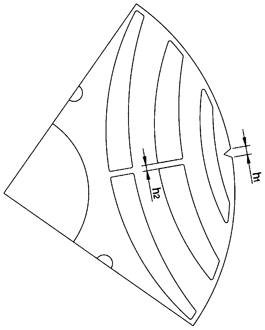
Synchronous reluctance motor rotor
A synchronous reluctance motor and rotor technology, applied in the direction of magnetic circuit rotating parts, magnetic circuits, electrical components, etc., can solve the problems of insufficient electromagnetic torque, low mechanical strength, and motor leakage inductance, so as to improve electromagnetic torque, Improved mechanical strength and reduced leakage inductance
- Summary
- Abstract
- Description
- Claims
- Application Information
AI Technical Summary
Problems solved by technology
Method used
Image

Examples
Embodiment Construction
[0023] The following will clearly and completely describe the technical solutions in the embodiments of the present invention with reference to the accompanying drawings in the embodiments of the present invention. Obviously, the described embodiments are only some, not all, embodiments of the present invention. Based on the embodiments of the present invention, all other embodiments obtained by persons of ordinary skill in the art without making creative efforts belong to the protection scope of the present invention.
[0024] The purpose of the present invention is to provide a synchronous reluctance motor rotor with high magnetic induction, high mechanical strength, high salient pole and high electromagnetic torque.
[0025] In order to make the above objects, features and advantages of the present invention more comprehensible, the present invention will be further described in detail below in conjunction with the accompanying drawings and specific embodiments.
[0026] Su...
PUM
 Abstract
Description
Claims
Application Information