Novel digestive-endoscope feeding apparatus

A feeding device and digestive endoscope technology, applied in endoscopy, medical science, surgery, etc., can solve the problems of easy jamming, unfavorable force detection of feeding device, unfavorable patient safety, etc., and achieve the effect of small size

Active Publication Date: 2019-10-25
HARBIN INST OF TECH
View PDF24 Cites 4 Cited by
  • Summary
  • Abstract
  • Description
  • Claims
  • Application Information

AI Technical Summary

Problems solved by technology

[0004] The technical problem to be solved in the present invention is: currently the existing feeding device for digestive endoscope adopts friction wheel to realize the feeding function of digestive endoscope, but the rotation of friction wheel will cause friction force at the same time, which is not conducive to the force detection of the feeding device. Moreover, it is easy to get stuck in an accidental situation, which is not conducive to the safety of patients; thereby providing a new type of digestive endoscope feeding device

Method used


Image

  • Novel digestive-endoscope feeding apparatus
  • Novel digestive-endoscope feeding apparatus
  • Novel digestive-endoscope feeding apparatus

Examples


specific Embodiment approach 1

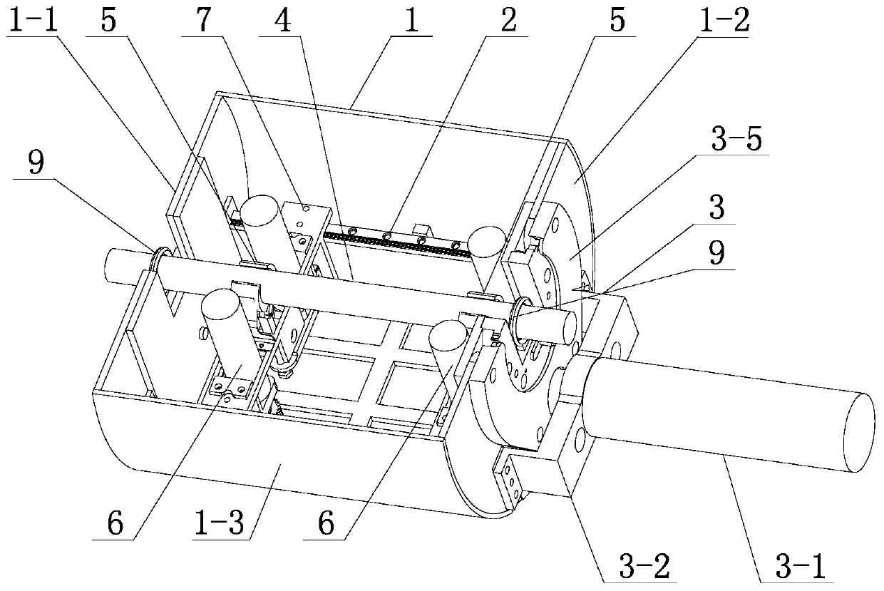
[0036] Specific implementation mode one: as figure 1 and figure 2 As shown, in this embodiment, the feeding device includes a fixed housing 1, a rotary mechanism, two clamping mechanisms 5, two feeding mechanisms 6, two upper slide plates 7 and four first sliders 8;

[0037] The fixed shell 1 includes a front fixed plate 1-1, a rear fixed plate 1-2 and an arc-shaped plate surface 1-3, the front fixed plate 1-1 and the rear fixed plate 1-2 are semicircular plates, and the front fixed plate 1-1 and the rear fixing plate 1-2 are matched with the arc openings on both sides of the arc-shaped plate surface 1-3, and the front fixing plate 1-1 and the rear fixing plate 1-2 are respectively fixed on the arc-shaped plate by screws In the arc-shaped mouth on both sides of surface 1-3;

[0038] The slewing mechanism includes a slewing frame body 2 and a drive assembly 3. The slewing frame body 2 is rotatably connected in the fixed shell 1, and the drive assembly 3 is fixed on the rear ...

specific Embodiment approach 2

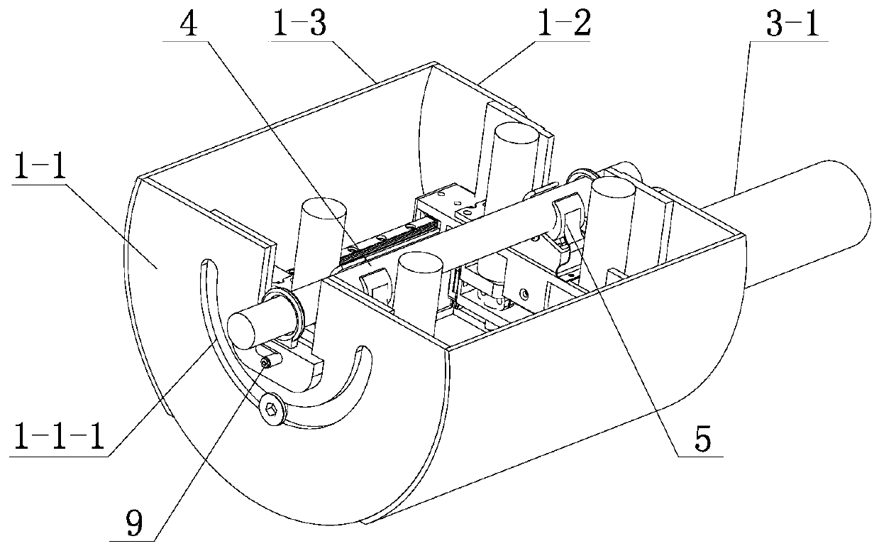
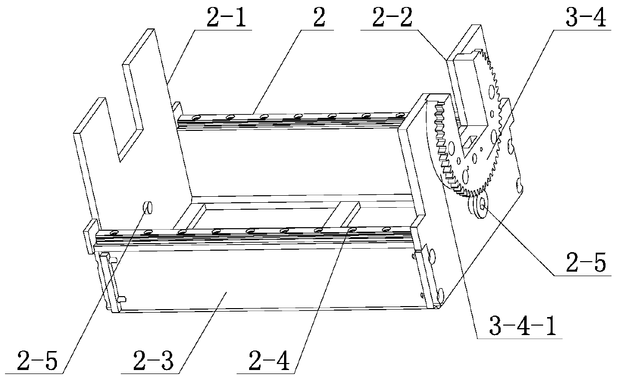
[0041] Specific implementation mode two: as image 3 As shown, in this embodiment, the slewing frame body 2 includes a front end plate 2-1, a rear end plate 2-2, two side vertical plates 2-3, two slide rails 2-4 and two sliding screws 2-5, two side vertical plates 2-3 are arranged vertically side by side, the front end plate 2-1 is fixed on the front ports of the two side vertical plates 2-3 by screws, and the rear end plate 2-2 is fixed on the front ports of the two side vertical plates 2-3 by screws. For the rear ports of the two side risers 2-3, a slide guide rail 2-4 is respectively fixed on the tops of the two side risers 2-3, at the positions opposite to the front end plate 2-1 and the rear end plate 2-2 Connect a slide screw 2-5 respectively;

[0042] Such as figure 2 As shown, the front fixed plate 1-1 has a first arc-shaped chute 1-1-1, and the rear fixed plate 1-2 has an arc-shaped gap and a second arc-shaped chute, and the second arc The arc-shaped chute is dire...

specific Embodiment approach 3

[0045] Specific implementation mode three: as figure 1 , image 3 and Figure 4 As shown, in this embodiment, the drive assembly 3 includes a first drive motor 3-1, a first drive motor fixing frame 3-2, an output gear 3-3 and a rotary gear 3-4, wherein the output gear 3- The outer diameter of 3 is smaller than that of the rotary gear 3-4. In order to ensure that the rotary speed of the rotary mechanism is within a safe range, the reduction ratio can be changed by replacing the output gear 3-3 and the rotary gear 3-4. ;

[0046] Such as image 3 As shown, one side of the rotary gear 3-4 is provided with a connecting block 3-4-1, and the rotary gear 3-4 is integrally made with the connecting block 3-4-1 on it, and the connecting block on the rotary gear 3-4 3-4-1 passes through the arc-shaped gap on the rear fixed plate 1-2 and is fixedly connected to the rear end plate 2-2 of the revolving frame body 2 through cylindrical pins;

[0047] Such as Figure 4 As shown, the fir...


PUM


Abstract

The invention discloses a novel digestive-endoscope feeding apparatus and belongs to the field of medicine instruments, aiming to solve problems that an existing digestive-endoscope feeding apparatusadopts a friction wheel to realize the feeding function, the rotation of the friction wheel causes friction force which is not conducive to the detection of force, and easy getting stuck by accident is not conductive to the safety of patients. The novel digestive-endoscope feeding apparatus comprises a fixed housing, a swing mechanism, two clamping mechanisms, two feeding mechanisms, two upper sliding plates and four first sliders; the swing mechanism includes a rotary frame and a drive assembly, the rotary frame is arranged in the fixed housing, the drive assembly is arranged outside the fixed housing, and the rotary frame performs rotary motion through the drive assembly; each of lower ends of two ends of each upper sliding plate is provided with a first slider fixedly, the upper slidingplates are respectively and sliably connected onto the upper end face of the rotary frame side by side through the first sliders at two ends of the upper sliding plate, and each upper sliding plate is provided with one clamping mechanism and one feeding mechanism. The novel digestive-endoscope feeding apparatus is used for feeding and outputting of the digestive endoscopy.

Description

technical field [0001] The invention belongs to the field of medical devices, in particular to a digestive endoscope feeding device for digestive endoscopy. Background technique [0002] The field of medical devices is an intersecting field between the medical field and the robotics field. It is a development trend to apply the advantages of the robotics field to the medical field. In the traditional digestive endoscopy, the doctor needs to hold the digestive endoscope to operate and swing. The doctor is prone to fatigue and trembling under the long-term working state, resulting in blurred and distorted images. With the development of science and technology, robotic medical assistance technology can be very good to solve these problems. The robot-assisted technology can provide a stable spatial posture, and the doctor can adjust the feeding degree and posture of the digestive endoscope by adjusting the switches and buttons, which can effectively reduce the doctor's fatigue....

Claims


Application Information

Patent Timeline
Patent Type & Authority Applications(China)
IPC IPC(8): A61B1/00
CPCA61B1/00131A61B1/00147
Inventor 付宜利潘博宋涛
Owner HARBIN INST OF TECH
Why Eureka
Try Eureka