Perforating structure used for laptop mold

A notebook computer and hole-opening structure technology, which is applied to machine tools, manufacturing tools, boring/drilling and other directions suitable for grinding the edge of workpieces, can solve the problems of complex processing procedures and low processing efficiency, and avoid flying around, Improve the effect of grinding and increase the surface roughness

Active Publication Date: 2019-10-25
重庆禾秀丰电子有限公司
View PDF8 Cites 3 Cited by
  • Summary
  • Abstract
  • Description
  • Claims
  • Application Information

AI Technical Summary

Problems solved by technology

[0003] The present invention intends to provide a hole structure for notebook computer molds, so as to solve the technical problems that in the prior art, after the mold is drilled, additional settings are required to polish the holes, resulting in complicated processing procedures and low processing efficiency

Method used


Image

  • Perforating structure used for laptop mold
  • Perforating structure used for laptop mold
  • Perforating structure used for laptop mold

Examples


Embodiment 1

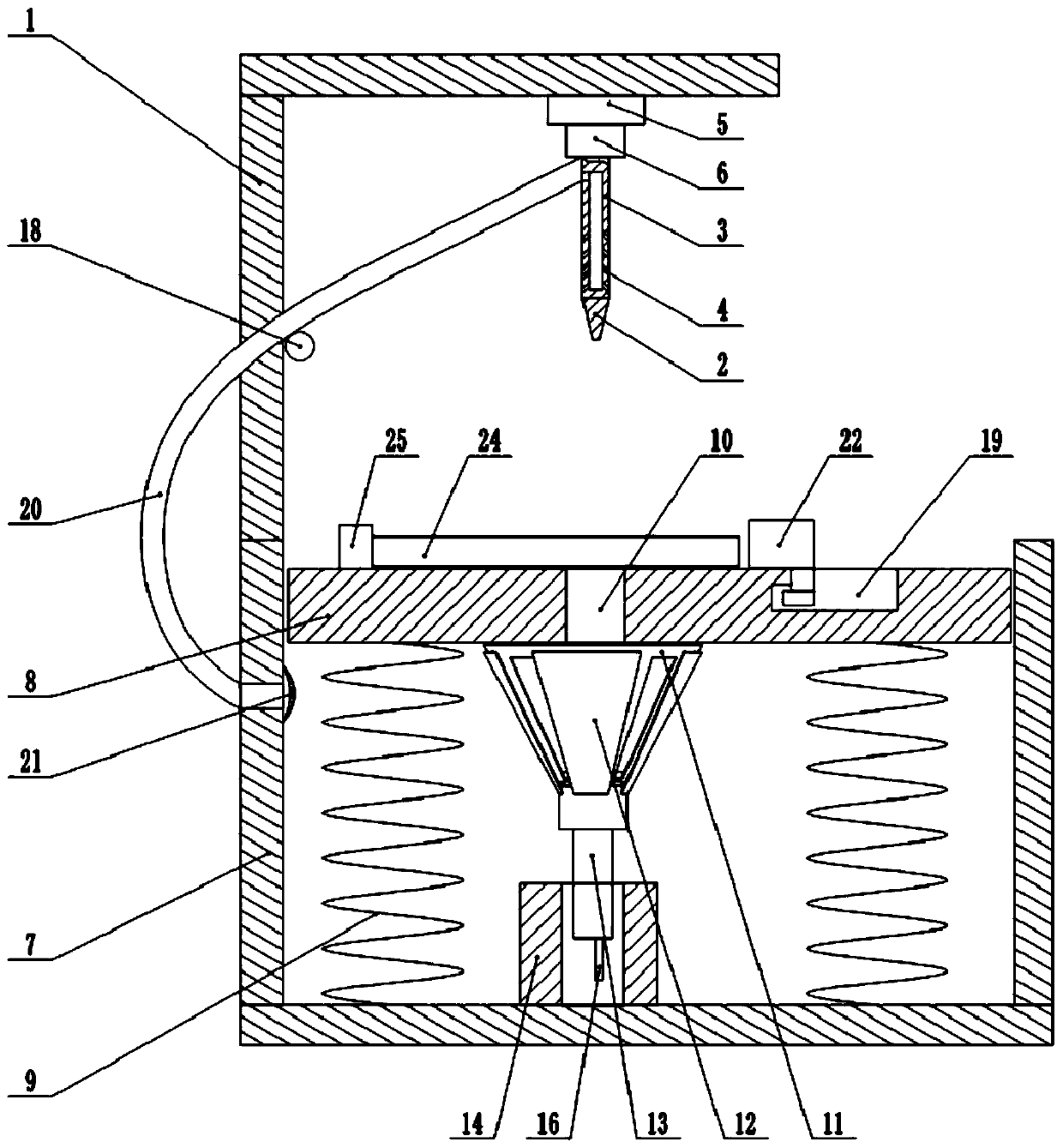
[0034] as attached figure 1 Shown: the opening structure used for notebook computer molds, including the frame 1 and the drill bit 2, the upper end of the drill bit 2 is fixedly clamped with a grinding rod 3, and a grinding hole 4 is opened on the peripheral wall of the grinding rod 3, and the grinding hole 4 is inclined toward Bottom setting; the upper end of the frame 1 is fixed with a cylinder 5 through bolts, and the telescopic rod 6 is slidably connected in the cylinder 5, and the lower end of the telescopic rod 6 is connected with a motor through bolts, and the output shaft of the motor is fixedly clamped with the upper end of the grinding rod 3 .

[0035] The lower side of the frame 1 is fixed with a collection box 7 by bolts, and the collection box 7 is vertically slidably connected with a load plate 8 through a guide rail. Welding, elastic part 9 is stage clip here; The outer peripheral cover of elastic part 9 is provided with the telescopic tube that is used to prev...

Embodiment 2

[0043] Such as Figure 5 As shown, the difference between this embodiment and Embodiment 1 is that the clamps include a first clamp and a second clamp 22. Here, for convenience of description, the one located on the upper side of the mold 24 is named the first clamp, and the one on the right side of the mold 24 is named the second clamp. Clamp 22, the first clamp and the second clamp 22 are respectively slidably connected with the carrier plate 8, and the sliding directions of the first clamp and the second clamp 22 are perpendicular to each other, the structure of the second clamp 22 of the first clamp is the same, here the first The structure of the clamp is described as an example. The first clamp is rotatably connected with a roller 23 through a bearing. When using this solution, the mold 24 is placed on the carrier plate 8, and the left side and the lower side of the mold 24 are against the side wall of the collection box 7, then the first clamp is slid downward, and the ...


PUM


Abstract

The invention relates to the technical field of machining of laptop molds, in particular to a perforating structure used for a laptop mold. The perforating structure comprises a rack and a drill bit.The drill bit is rotationally connected to the rack. A collection box is fixedly arranged on the lower side of the rack. A bearing plate is vertically connected in the collection box in a sliding manner. Elastic parts are fixedly arranged between the bearing plate and the collection box. A through hole is formed in the bearing plate and located under the drill bit. A control mechanism used for controlling opening and closing of the through hole is arranged on the lower side of the through hole. An air outlet is arranged on the collection box, and a one-way valve is arranged on the air outlet.A grinding rod is fixedly arranged at the upper end of the drill bit, and a grinding hole is formed in the peripheral wall of the grinding rod. Through the adoption of the scheme, the technical problems that in the prior art, after holes are drilled in the mold, the holes need to be ground through additional arrangement, consequently, machining procedures are complex, and machining efficiency is low can be solved.

Description

technical field [0001] The invention relates to the technical field of notebook computer mold processing, in particular to a hole structure for notebook computer molds. Background technique [0002] With the development of mechanical processing technology and the need to meet the production schedule, the application of molds in production is becoming more and more extensive. According to different products, different size and precision requirements, reasonable design of molds to solve production problems is very important for improving production efficiency and product quality. has an important role. Drilling is a relatively common and indispensable machining process. Most molds involve drilling. Simple drilling generally adopts fixture positioning, and manual operation directly drills holes; It is prone to the situation that the position of the processed hole deviates far from the required hole, which in turn affects the quality of the parts produced by the mold; the drill...

Claims


Application Information

Patent Timeline
Patent Type & Authority Applications(China)
IPC IPC(8): B23B41/00B23Q11/00B24B9/00B23Q3/06B23Q1/25
CPCB23B41/00B23B2270/08B23B2270/28B23B2270/62B23Q1/25B23Q3/06B23Q11/0046B23Q11/0067B24B9/00
Inventor 陈奕超贺申虎
Owner 重庆禾秀丰电子有限公司
Why Eureka
Try Eureka