Secondary line manufacturing system and method for electrical cabinet

A production method and secondary line technology, applied in the direction of electrical components, circuits, circuit/collector components, etc., can solve problems such as low work efficiency, error-prone, messy work site, etc., to achieve slow solution efficiency and reduce error rate , easy-to-understand effect

Pending Publication Date: 2019-10-25
SUZHOU CLOU MGE ELECTRIC
View PDF0 Cites 0 Cited by
  • Summary
  • Abstract
  • Description
  • Claims
  • Application Information

AI Technical Summary

Problems solved by technology

[0003] The realization of the function of the secondary equipment is mainly through the interconnection of the secondary wires between the components. The existing methods of making the secondary wires of the electrical cabinet are the preparation of the secondary wire cutting and the preparation of the marking number, and then the on-site wiring. Not only error-prone, but also low work efficiency and messy 5S on the job site

Method used


Image

  • Secondary line manufacturing system and method for electrical cabinet
  • Secondary line manufacturing system and method for electrical cabinet
  • Secondary line manufacturing system and method for electrical cabinet

Examples


Embodiment 1

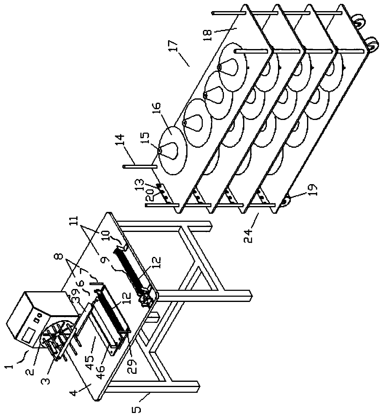
[0057] Depend on Figure 1-Figure 12 A kind of electrical cabinet secondary wire production system shown, comprises wire rack 17 and workbench 4, and workbench 4 and wire rack 17 are arranged at intervals left and right.

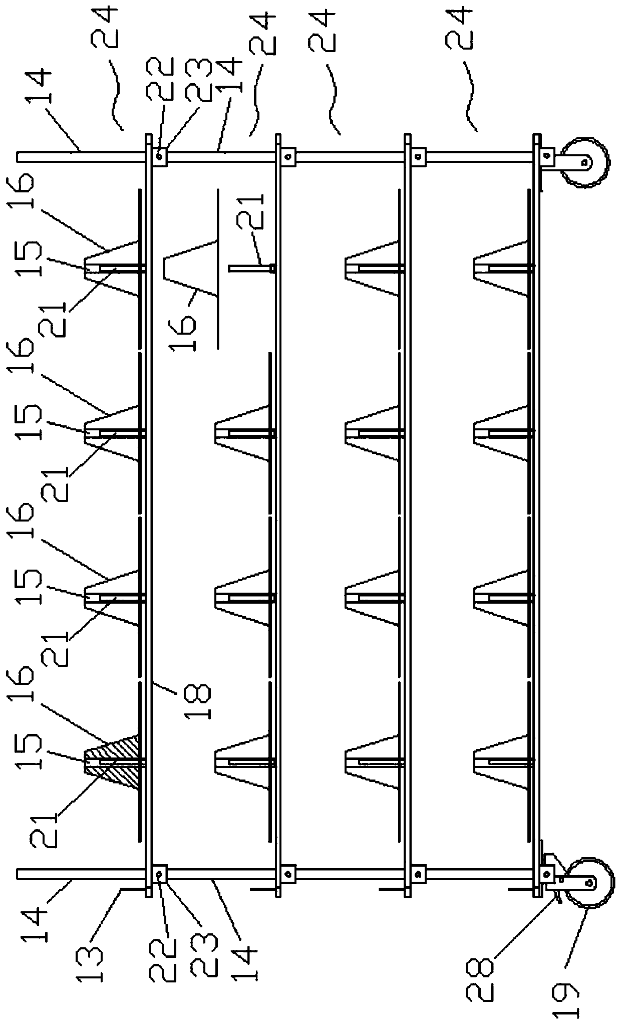
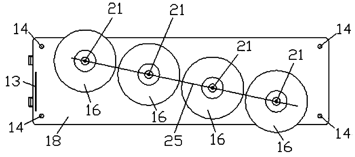
[0058] Several horizontal laminates 18 are sequentially arranged at intervals from top to bottom on the wire frame 17. Specifically, the wire frame 17 includes several laminate units 24 arranged sequentially from top to bottom, and the laminate units 24 include the layer Plate 18 and four pillars 14 are fixed on the upper side of the laminate 18, the laminate 18 is a rectangular plate extending vertically and horizontally on the left and right, and the four pillars 14 are respectively fixed at the four corners of the laminate 18, and the laminate 18 The bottom surface is provided with four protrusions 23, and each protrusion 23 is provided with a groove with a notch downward. In the upper and lower adjacent two-layer board units 24: the tops of the four pill...

Embodiment 2

[0066] Depend on Figure 13-Figure 30 As shown, the method for manufacturing the secondary wire of the electrical cabinet realized by using the secondary wire manufacturing system of the electrical cabinet described in Embodiment 1 includes the following steps:

[0067] (1) At least one wire reel 16 is wound with wires on the outer ring. The wires here are the secondary wires used to form the secondary wire harness. Since the secondary wires are bought, they are wound into rolls, so the secondary wires are directly placed outside the wire reel. Only one wire is wound on one wire reel. In this embodiment, several wire reels on the wire rack 17 are wound with wires, and the several wires wound on several wire reels 16 are pulled to the left and made They pass through several wire holes 20 respectively. The number of wires in a bundle of secondary wire harnesses is determined by the number of tooling. The wires on the upper wire reel on any layer pass through the wire holes on th...


PUM


Abstract

The invention discloses a secondary wire manufacturing system and method for an electrical cabinet, and belongs to the technical field of electrical cabinets. The system comprises a wire frame and a workbench; a laminate is arranged on the wire frame; a wire coil shaft is arranged at the upper side of the laminate, and a rotatable wire coil is arranged on the wire coil shaft; an electric winding machine, a wire harness cutting device and a wire harness branching mechanism are sequentially arranged on the workbench at intervals from left to right. The manufacturing method of the secondary lineof the electrical cabinet is achieved based on the system. The invention relates to the system and the method for manufacturing the secondary line of the electrical cabinet, which can improve the secondary line manufacturing efficiency.

Description

technical field [0001] The invention belongs to the field of electrical cabinets, and in particular relates to the field of a system and method for making secondary wires of an electrical cabinet. Background technique [0002] With the continuous development of the power industry, the quality, reliability and efficiency requirements of electrical equipment are getting higher and higher. Electrical equipment includes primary equipment and secondary equipment. Secondary equipment refers to the control, protection and monitoring of the work of primary equipment. and measuring equipment. [0003] The realization of the function of the secondary equipment is mainly through the interconnection of the secondary wires between the components. The existing methods of making the secondary wires of the electrical cabinet are the preparation of the secondary wire cutting and the preparation of the marking number, and then the on-site wiring. Not only is it easy to make mistakes, but the...

Claims


Application Information

Patent Timeline
IPC IPC(8): H01R43/28
CPCH01R43/28Y02W30/82
Inventor 朱国华宋亚艳
Owner SUZHOU CLOU MGE ELECTRIC
Why Eureka
Try Eureka