Parallel LED current-sharing circuit of motor driving system

An LED circuit and motor drive technology, applied in control systems, electric light sources, electrical components, etc., can solve problems such as accelerated LED aging or damage, and achieve the effects of improving reliability, improving current sharing, and saving costs.

Inactive Publication Date: 2019-10-25
BIGBEST SOLUTIONS
View PDF5 Cites 0 Cited by
  • Summary
  • Abstract
  • Description
  • Claims
  • Application Information

AI Technical Summary

Problems solved by technology

In addition, if there is current feedback, when a single LED is damaged, the current will be concentrated to flow to another LED, and the operating current will be several times that of the original, thus accelerating the aging or damage of the LED

Method used


Image

  • Parallel LED current-sharing circuit of motor driving system
  • Parallel LED current-sharing circuit of motor driving system

Examples


no. 1 example

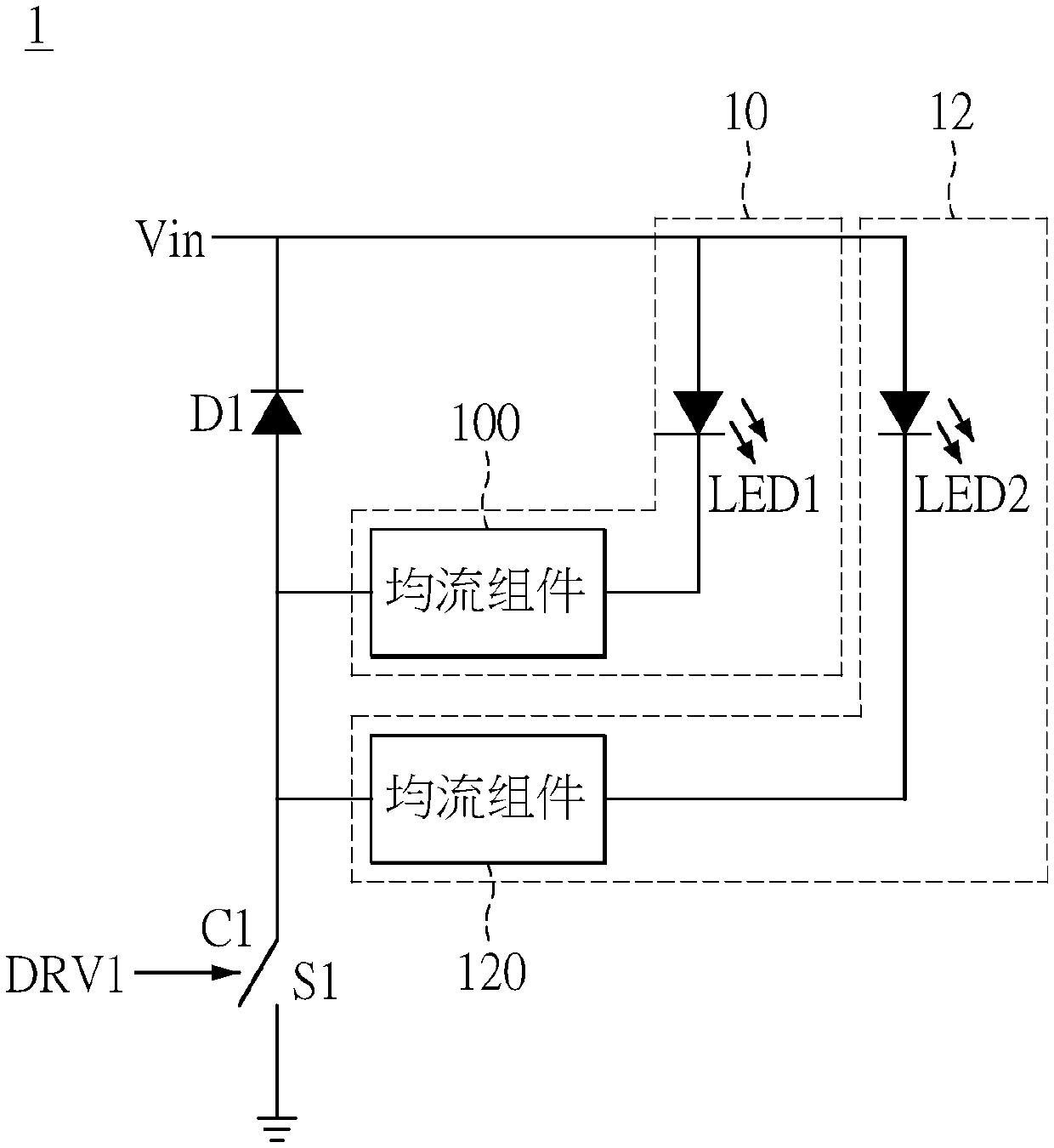
[0027] see figure 1 as shown, figure 1 It is a circuit layout diagram of a parallel LED current sharing circuit according to the first embodiment of the present invention. As can be seen from the above figures, the first embodiment of the present invention provides a parallel LED current equalizing circuit 1 , including LED circuits 10 and 12 connected in parallel, an input power source Vin, a switch component S1 and a diode D1. The LED circuit 10 includes a light emitting diode LED1 and a current equalizing component 100 connected in series with the light emitting diode LED1 , and the LED circuit 12 includes a light emitting diode LED2 and a current balancing component 120 connected in series with the light emitting diode LED2 . One end of the current equalizing component 100 is connected to the negative pole of the light emitting diode LED1, and one end of the current equalizing component 120 is connected to the negative pole of the light emitting diode LED2. The input pow...

no. 2 example

[0038] Please refer to figure 2 , figure 2 It is a circuit layout diagram of the parallel LED current sharing circuit of the motor driving system according to the second embodiment of the present invention. In this embodiment, similar to the first embodiment, similar component symbols represent similar components, and details are not repeated here.

[0039] As shown in the figure, the second embodiment of the present invention provides a parallel LED current sharing circuit 2 for a motor drive system, including LED circuits 20 and 22 connected in parallel, an input power supply Vin, an N-type MOS field effect transistor NM1, a diode D1 and Motor drive circuit 24.

[0040] The LED circuit 20 includes a light emitting diode LED1 and an inductor L1 connected in series with the light emitting diode LED1 , and the LED circuit 22 includes a light emitting diode LED2 and an inductor L2 connected in series with the light emitting diode LED2 . One ends of the inductors L1 and L2 a...


PUM


Abstract

The invention discloses a parallel LED current-sharing circuit of a motor driving system. The circuit comprises at least two LED circuits which are connected in parallel, an input power supply, a switch assembly, a diode and a motor driving circuit; each LED circuit comprises a light-emitting diode and a current-sharing assembly connected with the light-emitting diode in series, wherein one end ofthe current-sharing assembly is connected to the negative electrode of the light-emitting diode; the input power supply is connected to anodes of the light-emitting diodes; one end of the switch assembly is connected to the other end of each current-sharing assembly, and the other end is grounded; one end of the diode is connected to the input power supply, and the other end is connected to the switch assembly and connected in parallel with the at least two LED circuits. The first driving end of the motor driving circuit is connected with the control end of the switch assembly and outputs a first driving signal. Due to the adoption of an anti-buck power converter architecture, the motor driving circuit and the switch assembly are driven by a common-ground architecture, a driving power supply does not need to be additionally arranged, and the LED current can be determined by controlling the duty ratio of an output pulse modulation signal.

Description

technical field [0001] The invention relates to a parallel LED current equalizing circuit of a motor driving system, in particular to a parallel LED current equalizing circuit of a motor driving system comprising a motor driving circuit and a current equalizing component. Background technique [0002] LED lighting is gradually widely used in the lighting market because of power saving. LEDs have been actually used in some home appliances to provide auxiliary lighting for lamps. For example, range hoods usually have two LED lamps as auxiliary lighting. In order to improve reliability, current sharing technology should be used in such home appliances. [0003] Brushless DC motors have been introduced into the existing range hood applications. Generally, there will be a motor driver board. In addition to controlling the motor, the driver board power supply can also provide power for the LED drive circuit and the man-machine operation panel. Commercially available products have ...

Claims


Application Information

Patent Timeline
Patent Type & Authority Applications(China)
IPC IPC(8): H05B33/08H02P29/00H05B44/00
CPCH02P29/00H05B45/40
Inventor 邱嘉隆林志鸿柯柏年
Owner BIGBEST SOLUTIONS
Why Eureka
Try Eureka