High current constant current ultraviolet light control circuit

A control circuit and high-current technology, applied in the field of high-current constant-current ultraviolet control circuits, can solve the problems of complex drive circuit design, high cost, and increased current loss, and achieve the expansion of the adjustable range of the duty cycle and cost savings , The effect of reducing the loss of current

Active Publication Date: 2017-07-14
JIANGSU GULIDE PRECISION PHOTOELECTRIC
View PDF11 Cites 0 Cited by
  • Summary
  • Abstract
  • Description
  • Claims
  • Application Information

AI Technical Summary

Problems solved by technology

[0005] In ultraviolet curing irradiation equipment, the stable output current is relatively small, resulting in increased current loss, and the drive circuit design in the prior art is complex and costly

Method used


Image

  • High current constant current ultraviolet light control circuit
  • High current constant current ultraviolet light control circuit
  • High current constant current ultraviolet light control circuit

Examples


Embodiment 1

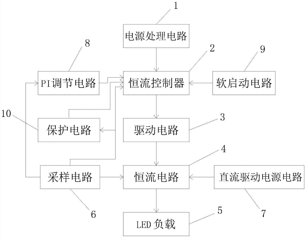
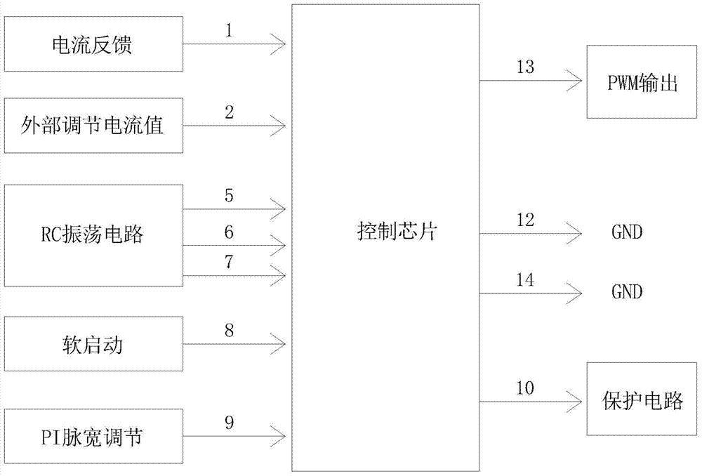
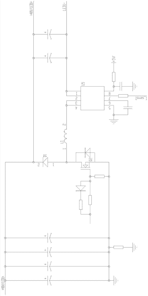
[0029] See figure 1 with figure 2 , the large current constant current ultraviolet light control circuit of this embodiment has a power processing circuit 1, a constant current controller 2, a drive circuit 3, a constant current circuit 4 and an LED load 5 connected in sequence; the input end of the constant current circuit 4 is also It is connected with the output end of the sampling circuit 6 and the DC drive power supply circuit 7; the output end of the sampling circuit 6 is connected with the input end of the constant current controller 2; the output end of the sampling circuit 6 is connected with the input end of the PI adjustment circuit 8; the PI adjustment The output end of the circuit 8 is connected to the input end of the constant current controller 2; the constant current circuit 4 includes a BUCK step-down topology circuit.

[0030] It also has a soft start circuit 9 and a protection circuit 10; the output end of the soft start circuit 9 is connected to the input...


PUM


Abstract

The invention relates to a large-current constant-current ultraviolet light control circuit, which has a power processing circuit, a constant-current controller, a drive circuit, a constant-current circuit and an LED load sequentially connected; the input end of the constant-current circuit is also connected with a sampling circuit, The output terminals of the DC driving power supply circuit are connected; the output terminals of the sampling circuit are connected with the input terminals of the constant current controller; the output terminals of the sampling circuit are connected with the input terminals of the PI regulation circuit; the output terminals of the PI regulation circuit It is connected with the input terminal of the constant current controller; the constant current circuit includes a BUCK step-down topology circuit. The invention can stably output a large current of 25A, reduce the loss of the current, simplify the design of the driving circuit and save the cost.

Description

technical field [0001] The invention relates to a large current constant current ultraviolet light control circuit. Background technique [0002] In line with the global trend of energy saving and emission reduction, in response to the curing needs of industries such as UV resins (inks, adhesives, coatings), the traditional high energy consumption and high pollution methods of curing with mercury lamps have become increasingly unsuitable for the development of the times In the current trend, there is an urgent need for an energy-saving and environmentally friendly cold light source used in electronics, spraying, printing and dyeing industries to replace traditional mercury lamp curing. [0003] With a series of advantages such as small size, solid state, long life, environmental protection, and power saving, LED has been widely used in various fields and has become one of the most promising high-tech fields in the 21st century. The United States, the European Union, Japan a...

Claims


Application Information

Patent Timeline
Patent Type & Authority Patents(China)
IPC IPC(8): H05B33/08H05B44/00
CPCH05B45/00
Inventor 蒋文贤宋金华宫宵宵
Owner JIANGSU GULIDE PRECISION PHOTOELECTRIC
Why Eureka
Try Eureka