Electrochromic element and electrochromic device including same

An electrochromic and electrochromic layer technology, applied in the directions of transportation and packaging, building components, vehicle components, etc., can solve the problems of low uniformity, increased power consumption, and the drive module is not effectively arranged with electrochromic equipment, etc. Achieve high discoloration uniformity and reduce power consumption

Active Publication Date: 2019-10-25
LEAPHIGH INC
View PDF6 Cites 5 Cited by
  • Summary
  • Abstract
  • Description
  • Claims
  • Application Information

AI Technical Summary

Problems solved by technology

[0004] In the case of electrochromic devices, since the discoloration occurs due to electrical power, there is the technical problem of having to properly control the applied voltage to achieve the desired degree of discoloration
[0005] Also, since electric power is required in the color changing process and maintenance process of the electrochromic device, there is a problem that power consumption increases as the area increases
[0006] Also, when the driving module for power supply is arranged in the electrochromic device, the driving module is not effectively arranged in the electrochromic device, and there is a problem that the inside of the electrochromic device becomes complicated
[0007] Also, since the electrochromic speed of the electrochromic element is slow and the uniformity of the electrochromic element is low, there is a problem that the performance of the application including the electrochromic element deteriorates

Method used


Image

  • Electrochromic element and electrochromic device including same
  • Electrochromic element and electrochromic device including same
  • Electrochromic element and electrochromic device including same

Examples


no. 1 example

[0258] 1. Electrochromic devices

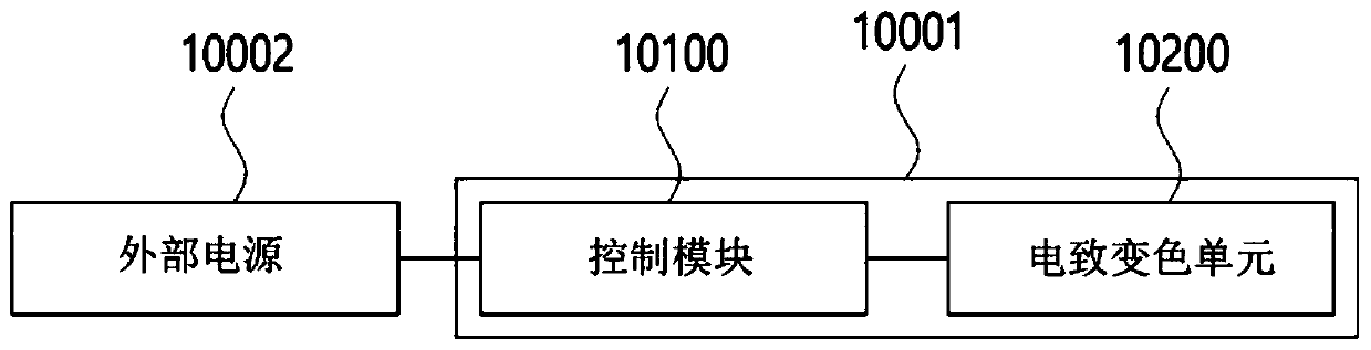
[0259] figure 1 is a diagram illustrating an electrochromic device according to an embodiment of the present application.

[0260] refer to figure 1 , an electrochromic device 10001 according to an embodiment includes a control module 10100 and an electrochromic element 10200 .

[0261] The electrochromic device 10001 can receive power from an external power source 10002.

[0262] An external power source 10002 can power the electrochromic device 10001. The external power supply 10002 can supply power to the control module 10100 . External power supply 10002 can provide voltage and / or current to control module 10100 . The external power supply 10002 may supply DC voltage or AC voltage to the control module 10100 .

[0263] The control module 10100 can control the electrochromic element 10200 . The control module 10100 may generate driving power based on power received from the external power source 10002 and provide the generated drivi...

no. 2 example

[1159] Hereinafter, another embodiment of the above-mentioned electrochromic element will be described.

[1160] In the following, the "optical state" of a configuration may be defined as a meaning encompassing properties of the configuration related to light. The optical state may include refractive index, transmittance (transmittance), color efficiency, optical density, color index, discoloration / bleaching state, and the like.

[1161] Hereinafter, "a change in the optical state" may refer to a change in the above-mentioned optical state. However, hereinafter, a change in an optical state refers to a change in a discoloration / decolorization state unless specifically mentioned.

[1162] Hereinafter, "differentiation" may refer to visual distinction. When distinguishing one configuration from another, it is possible to visually distinguish that configuration from the other configurations. In other words, when distinguishing the configuration from other configurations, the c...

no. 3 example

[1447] Hereinafter, an electrochromic device according to a third embodiment group will be described.

[1448] Figure 89 is a diagram illustrating the electrochromic device according to the first embodiment.

[1449] refer to Figure 89 , the electrochromic device 40001 according to the first embodiment includes an electrochromic element 40100 .

[1450]The electrochromic element 40100 may include a substrate 40110 , a transparent electrode 40120 , a first electrochromic layer 40130 , an ion transport layer 40140 , a second electrochromic layer 40150 and a reflective layer 40160 .

[1451] The electrochromic element 40100 may be connected to a driving circuit 40170 . The drive circuit 40170 may be electrically connected to the electrochromic element 40100 through a wire 40180 .

[1452] The driving circuit 40170 may be disposed in a region adjacent to the reflective layer 40160 . The distance between the driving circuit 40170 and the first electrochromic layer 40130 may ...


PUM

PropertyMeasurementUnit
reflectanceaaaaaaaaaa

Abstract

An embodiment of the present application provides an electrochromic device comprising an electrochromic element, wherein the electrochromic element enters a second state when a first voltage is applied to the electrochromic element in a state where the electrochromic element has a first state, and the electrochromic element enters a third state when the first voltage is applied to the electrochromic element in a state where the electrochromic element has a fourth state.

Description

technical field [0001] The present application relates to an electrochromic element and an electrochromic device comprising the electrochromic element, and more particularly, to an electrochromic element whose optical state changes and an electrochromic device for changing the optical state of the electrochromic element . Background technique [0002] Electrochromism is a phenomenon in which color changes based on an oxidation-reduction (redox) action caused by applied electric power. Materials that can be electrochromic can be defined as electrochromic materials. An electrochromic material has a property of not displaying a color when no power is applied to it from the outside and then displaying a color when power is applied thereto, or conversely, displaying a color when no power is applied to it from the outside and then displaying a color when power is applied thereto does not display the properties of the color. [0003] Electrochromic devices comprising electrochro...

Claims


Application Information

Patent Timeline
Patent Type & Authority Applications(China)
IPC IPC(8): G02F1/163E06B3/67B60R1/08G02F1/1514G02F1/1523G02F1/1524
CPCG02F1/1508G02F1/1514G02F1/1523G02F1/1524G02F1/1525G02F1/153G02F1/155G02F1/163G09G3/19B60R1/088B62D7/148E06B3/6722G02F2001/1502G09G2330/021
Inventor 朴翔显金炳东金贤钟金缀焕俞尚佑崔允喆金成中全光辰孔炫竣孙辰儿
Owner LEAPHIGH INC
Why Eureka
Try Eureka