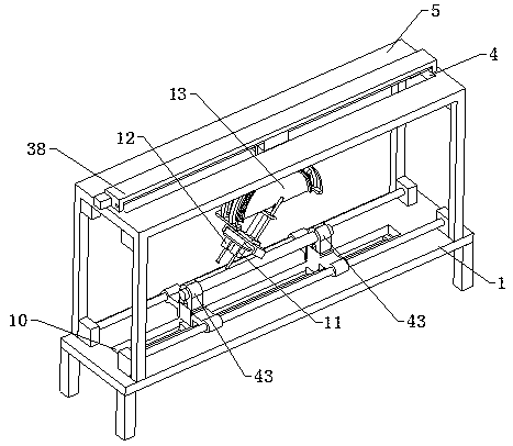
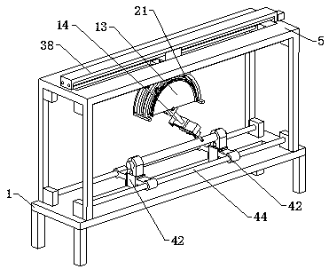
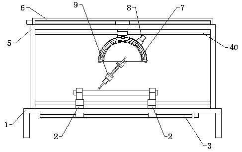
Shaft workpiece automatic inclined hole drilling device

A shaft workpiece, automatic drilling technology, applied in the direction of drilling/drilling equipment, metal processing equipment, boring/drilling, etc., can solve the deflection of the drill bit, affect the efficiency of processing, and cannot enter the shaft workpiece, etc. question

Inactive Publication Date: 2019-10-29
云和县凯毅德电子设备厂
View PDF0 Cites 22 Cited by
  • Summary
  • Abstract
  • Description
  • Claims
  • Application Information

AI Technical Summary

Problems solved by technology

[0002] In mechanical processing, it is often necessary to process some inclined holes on shaft workpieces. The existing drilling equipment cannot adjust the angle of the drill bit because the drill bit is in the vertical direction. Usually, the inclined holes are drilled manually. First, the shaft workpiece Fix it, and then drill the inclined hole by manually holding the drilling machine tilted. In this way, first, the drill bit will easily cause the drill bit to deflect when drilling, and then cannot enter the shaft workpiece. Second, the inclined hole The angle is not easy to control. Thirdly, it increases the labor force and affects the efficiency of processing. Therefore, we propose an automatic drilling equipment for inclined holes in shaft workpieces to solve the above-mentioned problems.

Method used


Image

  • Shaft workpiece automatic inclined hole drilling device
  • Shaft workpiece automatic inclined hole drilling device
  • Shaft workpiece automatic inclined hole drilling device

Examples


Embodiment Construction

[0026] The technical solutions of the present invention will be further described below in conjunction with the accompanying drawings and through specific implementation methods.

[0027] Wherein, the accompanying drawings are only for illustrative purposes, showing only schematic diagrams, rather than physical drawings, and should not be construed as limitations on this patent; in order to better illustrate the embodiments of the present invention, some parts of the accompanying drawings will be omitted, Enlargement or reduction does not represent the size of the actual product; for those skilled in the art, it is understandable that certain known structures and their descriptions in the drawings may be omitted.

[0028] In the drawings of the embodiments of the present invention, the same or similar symbols correspond to the same or similar components; , "inner", "outer" and other indicated orientations or positional relationships are based on the orientations or positional ...


PUM


Abstract

The invention relates to the field of shaft workpiece machining, in particular to a shaft workpiece automatic inclined hole drilling device. The shaft workpiece automatic inclined hole drilling devicecomprises a workbench, and further comprises a discharge locating mechanism, a horizontal moving mechanism and an adjusting mechanism. The discharge locating mechanism comprises two clamping assemblies and a face-to-face adjusting assembly. The workbench is provided with a rectangular avoidance port. The horizontal moving mechanism comprises a horizontal support and a horizontal moving assembly.The adjusting mechanism comprises an angular adjusting assembly, a push assembly and a horizontal driving assembly. The horizontal support is provided with an avoidance penetration port used for avoiding the angular adjusting assembly during moving. The working end of a longitudinal driving assembly comprises a main drilling motor and an auxiliary drilling motor. The main drilling motor and the auxiliary drilling motor are symmetrically arranged at the working end of the longitudinal driving assembly in a spaced mode. The shaft workpiece automatic inclined hole drilling device can conduct inclined hole drilling by adjusting the angle at random and can improve the hole precision and the machining efficiency.

Description

technical field [0001] The invention relates to the field of shaft workpiece processing, in particular to an automatic inclined hole drilling device for shaft workpieces. Background technique [0002] In mechanical processing, it is often necessary to process some inclined holes on shaft workpieces. The existing drilling equipment cannot adjust the angle of the drill bit because the drill bit is in the vertical direction. Usually, the inclined holes are drilled manually. First, the shaft workpiece Fix it, and then drill the inclined hole by manually holding the drilling machine tilted. In this way, first, the drill bit will easily cause the drill bit to deflect when drilling, and then cannot enter the shaft workpiece. Second, the inclined hole The angle is not easy to control. Thirdly, the labor force is increased and the processing efficiency is affected. Therefore, we have proposed an automatic inclined hole drilling equipment for shaft workpieces in order to solve the abo...

Claims


Application Information

Patent Timeline
Patent Type & Authority Applications(China)
IPC IPC(8): B23B41/00B23Q1/26B23Q3/08
CPCB23B41/00B23Q1/26B23Q3/064B23Q3/08B23Q2703/04
Inventor 朱海艳
Owner 云和县凯毅德电子设备厂
Why Eureka
Try Eureka