Polishing workbench

A workbench and operating table technology, applied in the direction of grinding workpiece supports, grinding machines, manufacturing tools, etc., can solve problems such as affecting grinding efficiency, unfavorable use, unfavorable long-term use, etc., and achieve the effect of ensuring accuracy and grinding efficiency.

Inactive Publication Date: 2019-10-29
安徽建发电气设备有限公司
View PDF6 Cites 6 Cited by
  • Summary
  • Abstract
  • Description
  • Claims
  • Application Information

AI Technical Summary

Problems solved by technology

[0004] 1. When the existing device is in use, when grinding different parts, different devices are required for grinding due to the different parts, which not only wastes time, but also can only polish one at a time, and wastes grinding efficiency, which is not conducive to long-term time use;
[0005] 2. When the existing device is in use, due to the different positions of the grinding parts, it is necessary to manually control the grinding machine. Long-term use will make the operator feel out of force, which will affect the grinding efficiency. Even after long-term operation, the operator will cause Grinding errors cause resource loss, which is not conducive to use

Method used


Image

  • Polishing workbench
  • Polishing workbench
  • Polishing workbench

Examples


Embodiment 1

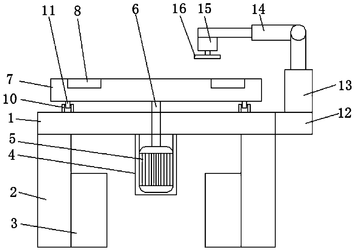
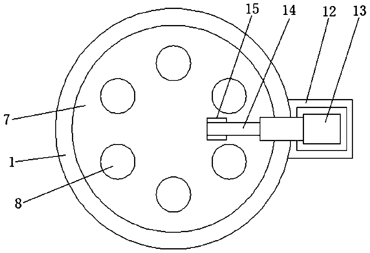
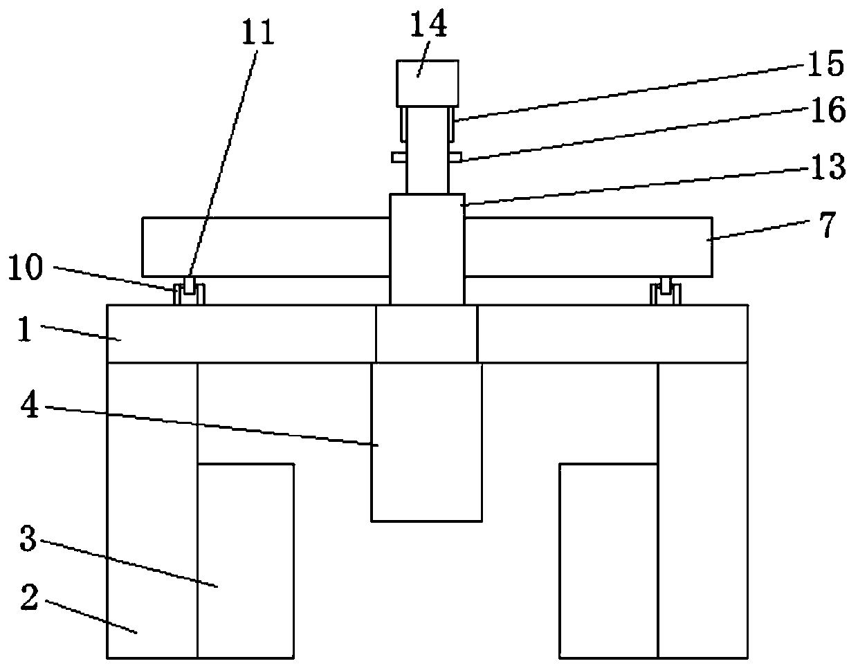
[0026] see Figure 1-4 , the present invention provides the following technical solutions: a grinding workbench, including a console 1, a fixed foot 2 is fixedly connected around the bottom of the console 1, a storage box 3 is movably connected to the inner side of the fixed leg 2 through a chute, and the bottom of the console 1 The center is fixedly connected with a motor box 4 by bolts, the inner cavity of the motor box 4 is fixedly connected with a rotating motor 5, the center of the top of the rotating motor 5 is movably connected with a rotating shaft 6, and the rotating shaft 6 runs through the center of the console 1, and the top of the rotating shaft 6 is fixedly connected with a The turntable 7, the turntable 7 is located above the operating table 1, the top of the turntable 7 is provided with a circular groove 8, the center of the top of the turntable 7 is fixedly connected with a fixed column 9, and the top of the operating table 1 is fixedly connected with a support...


PUM


Abstract

The invention belongs to the technical field of machining, in particular to a polishing workbench. The polishing workbench comprises an operation table, wherein the operation table is connected with amotor box. The cavity of the motor box is connected with a rotating motor, wherein the top of the rotating motor is connected with a rotating shaft, the top of the rotating shaft is connected with aturntable, and circular grooves are formed in the top of the turntable. The operation table is fixedly connected with a supporting plate, wherein the top of the supporting plate is fixedly connected with a vertical telescopic rod, the top of the vertical telescopic rod is connected with a transverse telescopic rod, and the transverse telescopic rod is connected with a polishing motor. According tothe polishing workbench, through arranging fixing devices, the cavities of the circular grooves are matched with external fixing devices in structure, in this way, to-be-polished pieces are fixed through the different fixing devices, which is convenient for the different pieces to be polished; and in addition, through arranging the telescopic rods, the polishing motor is controlled by the vertical telescopic rod to move up and down and controlled by the transverse telescopic rod to move left and right, which is convenient for a polishing disc to be controlled, and the polishing for specific locations of the pieces can be realized.

Description

technical field [0001] The invention belongs to the technical field of mechanical processing, and more specifically relates to a grinding workbench. Background technique [0002] Generally speaking, after the main part of some parts is processed, due to the requirements of surface roughness, it is often necessary to further polish the special surface of the parts. The traditional processing method is to manually send the parts to the grinding wheel for processing. Grinding, but this grinding method not only has poor grinding stability, but also has certain risks in operation. [0003] There are following problems in existing technology: [0004] 1. When the existing device is in use, when grinding different parts, different devices are required for grinding due to the different parts, which not only wastes time, but also can only polish one at a time, and wastes grinding efficiency, which is not conducive to long-term time use; [0005] 2. When the existing device is in u...

Claims


Application Information

Patent Timeline
Patent Type & Authority Applications(China)
IPC IPC(8): B24B19/00B24B27/00B24B41/00B24B41/06B24B47/00B24B47/22
CPCB24B19/00B24B27/0069B24B41/00B24B41/06B24B47/00B24B47/22
Inventor 周鲁育
Owner 安徽建发电气设备有限公司
Why Eureka
Try Eureka