Eureka AIR delivers breakthrough ideas for toughest innovation challenges, trusted by R&D personnel around the world.

Quick-change oil and gas sealing system for high-speed wire rod mill

A high-speed wire and sealing system technology, applied in the direction of engine sealing, mechanical equipment, engine components, etc., can solve the problems of aging and deformation of the sealing ring, entering the lubricating oil tank, and sealing effect failure, so as to improve the sealing effect and reduce the processing difficulty. , the effect of reducing the likelihood

Pending Publication Date: 2019-10-29
HENGSHUI HXT HYDRAULIC MACHINERY
View PDF9 Cites 3 Cited by
  • Summary
  • Abstract
  • Description
  • Claims
  • Application Information

AI Technical Summary

Problems solved by technology

[0005] Although the sealing member of the high-speed wire rod finishing mill with the above structure basically solves the sealing problem between the eccentric disc and the roll shaft, it is difficult for the cooling water on one side to enter the other side through the sealing mechanism arranged between the roll shaft and the eccentric disc. In the lubricating oil tank, but because the cooling water is still driven to form a high-speed swirl and enter the labyrinth structure when the roll shaft rotates at a high speed, forming a high-pressure water flow, it still has the possibility of entering the lubricating oil tank; in addition, the eccentric disc and "8 There is only one or several sealing rings between the word plates, but the sealing effect will fail immediately due to the aging and deformation of the sealing rings over time

Method used


Image

  • Quick-change oil and gas sealing system for high-speed wire rod mill
  • Quick-change oil and gas sealing system for high-speed wire rod mill
  • Quick-change oil and gas sealing system for high-speed wire rod mill

Examples


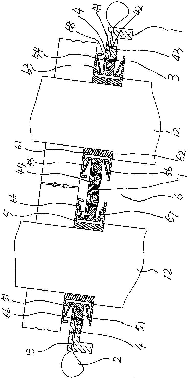
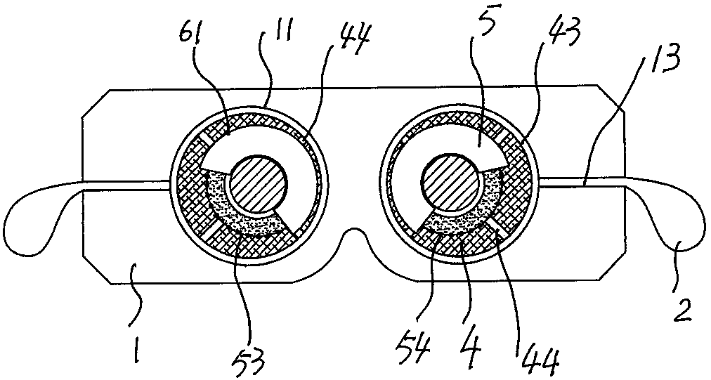
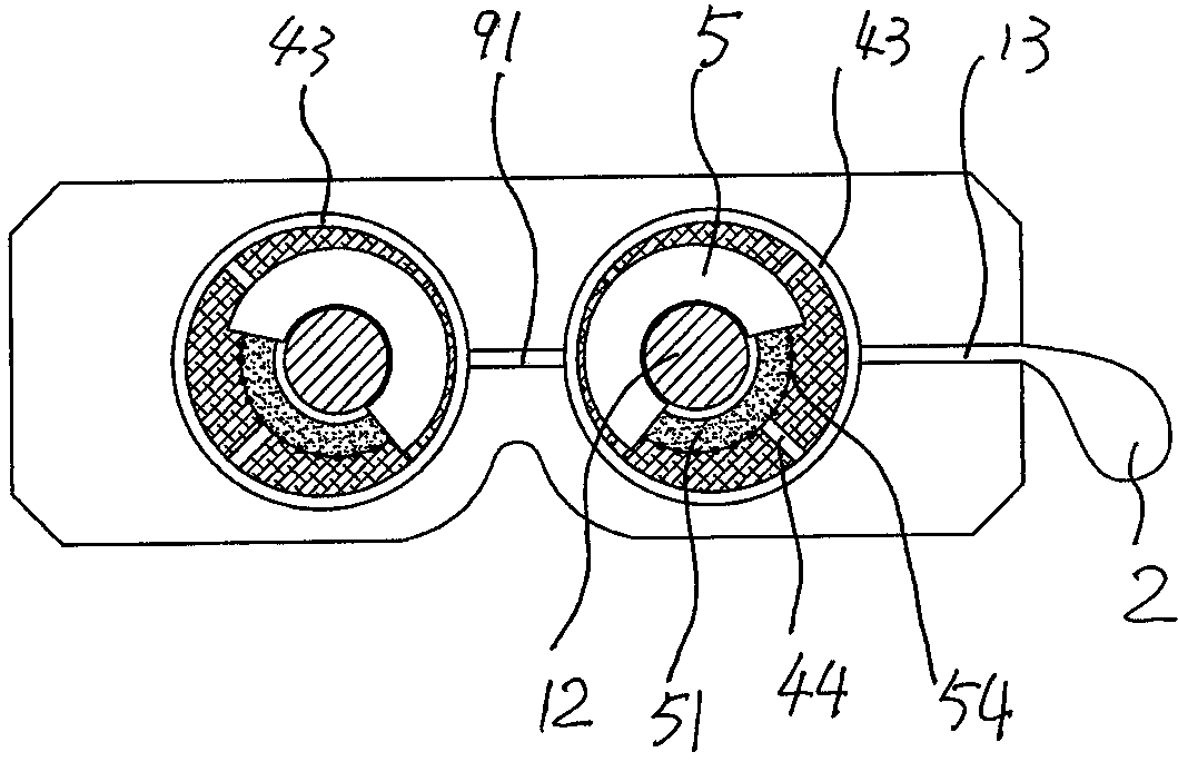
Embodiment Construction

[0027] The structure and working principle of the quick-change oil-gas sealing system for a high-speed wire rolling mill provided by the present invention will be further described in detail below in conjunction with the accompanying drawings.

[0028] As shown in Figures 1, 2 and 3, it is a schematic structural diagram of the working principle of the quick-change oil-gas sealing system for a high-speed wire mill provided by the present invention. The structure constituting the quick-change oil-gas sealing system includes: two left and right "8"-shaped plates 1 for fixing the shaft holes 11 of the roll shaft are provided, and the two shaft holes are respectively provided with shafts for adjusting the left and right roll shafts. The eccentric disc 4 (also known as "quick-change oil-gas sealing plate") with a distance of 12 shafts is set on the sealing mechanism 5 in the eccentric disc; two seals are arranged on the outer circle of the above-mentioned eccentric disc, which can be...


PUM


Abstract

The invention belongs to the technical field of wire rod mill accessories, and particularly relates to a quick-change oil and gas sealing system for a high-speed wire rod mill. According to the technical scheme of the sealing system, two 8-shaped plates for fixing shaft holes of roller shafts are arranged; an eccentric disc for adjusting the shaft interval of the roller shafts and a sealing mechanism sleeved with the eccentric disc are arranged in the shaft holes; the plate walls of one end side or / and two end sides of the 8-shaped plates are internally provided with air holes capable of beingconnected with an external air source; a disc body of the eccentric disc is internally provided with a radial internal blowing oil and gas path communicating with the air holes; an inner circle forming the eccentric disc is provided with an air flow outer ring groove corresponding to the internal blowing oil and gas path; and a plurality of high-pressure air flow blocking slotted holes are formedin the water cooling direction of the inner circle forming the eccentric disc. Through the system, cooling water can be effectively prevented from entering a labyrinth structure, and the isolation and sealing effects between cooling water and lubricating oil of the high-speed wire rod mill are improved.

Description

technical field [0001] The invention belongs to the technical field of wire rod mill accessories, in particular to a quick-change oil-gas sealing system for a high-speed wire rod mill. Background technique [0002] The oil-air sealing system for high-speed wire rod mills is an accessory used in the fifth-generation or sixth-generation metal wire rod finishing mills. It is mainly used for the isolation and sealing of the cooling water of the rolling ring and the lubricating oil in the roll box. The structure constituting the system includes two "8" plates for fixing the shaft holes of the roll shaft, and a sealing mechanism composed of an eccentric disc for adjusting the distance between the shaft shafts of the rolls and a sealing bracket sleeved in the shaft holes. . In order to improve its sealing effect, the Chinese patent application number is [0003] —— ZL201610172342.0, the invention patent application with publication (announcement) number CN105570467A discloses a s...

Claims


Application Information

Patent Timeline
IPC IPC(8): F16J15/447F16J15/46F16J15/40F16J15/3268F16J15/3284
CPCF16J15/4476F16J15/46F16J15/40F16J15/3268F16J15/3284
Inventor 宋阳
Owner HENGSHUI HXT HYDRAULIC MACHINERY
Why Eureka
Eureka Blog
Learn More