LED down lamp

A technology of LED downlight and LED light source, applied in lampshade, loss prevention measures of lighting device, cooling/heating device of lighting device, etc., can solve the problems of complicated structure design, general heat dissipation efficiency, insufficient uniformity and softness of light output, etc. Achieve the effect of novel and reasonable structure and light distribution method, simple and quick assembly and disassembly, and high heat conduction and heat transfer efficiency.

Inactive Publication Date: 2019-10-29
区月女
View PDF0 Cites 0 Cited by
  • Summary
  • Abstract
  • Description
  • Claims
  • Application Information

AI Technical Summary

Problems solved by technology

[0002] The light transmission cover of the current LED downlight is a planar structure embedded in the installation ring. The light is irradiated outward through the planar light transmission cover. The light from the light source can only be directly irradiated outward after passing through the light distribution of the light-transmitting cover once. The light angle is small, the light utilization rate is low, the light effect is average, and the light output is not uniform and soft enough, which is easy to dazzle the eyes.
In addition, the existing LED downlights generally have the problems of average heat dissipation efficiency, poor heat dissipation effect, cumbersome and complicated structural design, tedious and time-consuming assembly and disassembly, and high production costs.

Method used


Image

  • LED down lamp
  • LED down lamp

Examples


Embodiment Construction

[0012] It should be understood that the specific embodiments described here are only used to explain the present invention, not to limit the present invention.

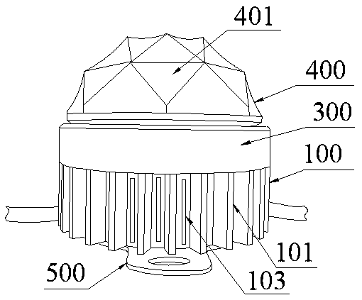
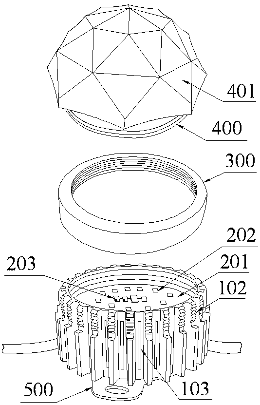
[0013] refer to Figure 1 to Figure 2 , an embodiment of an LED downlight according to the present invention is proposed, which includes a hollow cylindrical lamp housing 100, an LED light source control structure integrated with a light source and a driving circuit in the cylindrical lamp housing 100, and a threaded connection. The installation ring 300 fixed on the upper end of the cylindrical lamp housing 100, the hemispherical light-transmitting cover 400 which plays the role of light guide and light transmission, is screwed and fixed on the inner side wall of the upper end of the cylindrical lamp housing 100 and covered on the LED light source control structure, The base plate 500 installed on the bottom of the cylindrical lamp housing 100 .

[0014] A number of heat dissipation columns extend inward from the in...


PUM


Abstract

The invention discloses an LED down lamp. The LED down lamp comprises a cylindrical lamp shell, an LED light source control structure, an installation ring, a hemispherical light transmission cover and a bottom plate; the LED light source control structure is arranged in the cylindrical lamp shell; the installation ring is in threaded connection with the upper end of the cylindrical lamp shell; several heat dissipation columns inwardly extend on the inner side wall of the cylindrical lamp shell; the LED light source control structure comprises a substrate, several LED lamp beads and a drivingcircuit; the substrate is installed and fixed on the upper end faces of the heat dissipation columns; the driving circuit is arranged on the substrate, and electrically connected with the LED lamp beads; a glue filling layer for sealing the LED light source control structure is arranged in the cylindrical lamp shell; heat dissipation fins outwardly extend on the outer side wall of the cylindricallamp shell; heat dissipation threads are arranged at the upper parts of the heat dissipation fins; the heat dissipation threads are in threaded connection with the inner side wall of the installationring; several heat dissipation strip holes connected to the interior and capable of performing ventilation convection are arranged on the side wall of the cylindrical lamp shell; the hemispherical light transmission cover is made of a light transmission and light guide material; triangular light transmission surfaces are uniformly arranged on the surface of the hemispherical light transmission cover; and the surfaces of the triangular light transmission surfaces are arc concave surfaces.

Description

technical field [0001] The invention relates to the technical field of lamps, in particular to an LED downlight. Background technique [0002] The light transmission cover of the current LED downlight is a planar structure embedded in the installation ring. The light is irradiated outward through the planar light transmission cover. The light from the light source can only be directly irradiated outward after passing through the light distribution of the light-transmitting cover once. The light-emitting angle is small, the light utilization rate is low, the light effect is average, and the light output is not uniform and soft enough, which is easy to dazzle the eyes. In addition, the existing LED downlights generally have the problems of average heat dissipation efficiency, poor heat dissipation effect, cumbersome and complicated structural design, tedious and time-consuming assembly and disassembly, and high production costs. [0003] Therefore, how to realize a novel and ...

Claims


Application Information

Patent Timeline
Patent Type & Authority Applications(China)
IPC IPC(8): F21S8/02F21V29/80F21V19/00F21V31/04F21V29/77F21V17/12F21V29/83F21V3/02F21V3/06F21V15/01F21V29/89F21Y115/10
CPCF21S8/02F21V3/02F21V3/06F21V15/01F21V17/12F21V19/0025F21V29/77F21V29/80F21V29/83F21V29/89F21V31/04F21Y2115/10
Inventor 区月女
Owner 区月女
Why Eureka
Try Eureka