Hybrid electric vehicle energy flow demonstration controller system

A hybrid vehicle, energy flow technology, applied in the direction of instruments, educational appliances, teaching models, etc., can solve problems such as hidden safety hazards and operational errors, and achieve the effect of avoiding misoperation

Inactive Publication Date: 2019-10-29
WUHAN UNIV OF TECH
View PDF6 Cites 0 Cited by
  • Summary
  • Abstract
  • Description
  • Claims
  • Application Information

AI Technical Summary

Problems solved by technology

Finally, we are usually unable to judge that the car in the experimental teaching is working in a certain working mode, which is likely to cause operational errors and potential safety hazards

Method used


Image

  • Hybrid electric vehicle energy flow demonstration controller system
  • Hybrid electric vehicle energy flow demonstration controller system
  • Hybrid electric vehicle energy flow demonstration controller system

Examples


Embodiment Construction

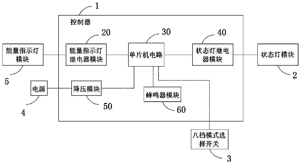
[0024] A frame structure diagram of a hybrid electric vehicle energy flow demonstration controller system implemented according to the present invention. In this embodiment, 1 is a controller, 2 is a status lamp module, 3 is an eight-speed mode selection switch, 4 is a system power supply, and 5 is an energy indicator module; the controller 1 is connected with the external status lamp module 2, the external The eight-speed mode selection switch 3, the external power supply 4, and the external energy indicator module 5 are respectively connected, and the controller 1 includes an energy indicator relay module 20, a single-chip circuit 30, a status light module 40, a step-down module 50 and a buzzer device module. The controller 1 is used to control the working state of the energy indicator module 5 in the energy flow demonstration system according to the working mode of the hybrid vehicle set by the eight-speed mode selection switch 3, and the different energy indicator lights c...


PUM


Abstract

The invention provides a hybrid electric vehicle energy flow demonstration controller system comprising an energy indicator light relay module, a single-chip microcomputer circuit, a state lamp relaymodule, a voltage reduction module and a buzzer module. By capturing eight-gear mode switch signals, it is ensured that each mode indicator light is lightened, and the working state and the energy flow direction of the hybrid electric vehicle in each mode are clearly displayed, various modes are ensured to work independently and do not interfere with each other; misoperation is avoided; and the hybrid electric vehicle energy flow demonstration controller system is safe and reliable.

Description

technical field [0001] The invention belongs to the technical field of teaching and training platforms for hybrid electric vehicles, and in particular relates to a control device for demonstration of energy flow of hybrid electric vehicles. Background technique [0002] A hybrid vehicle has multiple working modes, especially a fuel cell hybrid vehicle, which is equipped with an engine, a fuel cell, and a storage battery. The direction of energy flow is different when the car is starting, idling, starting, accelerating, constant speed, climbing, full speed, parking and other working conditions, and the real car demonstration cannot clearly indicate the direction of energy flow. At the same time, each energy flow module needs to be independently controlled for classification experiments. Finally, we are usually unable to judge that the car in the experimental teaching is working in a certain working mode, which is likely to cause operational errors and potential safety haza...

Claims


Application Information

Patent Timeline
Patent Type & Authority Applications(China)
IPC IPC(8): G09B25/00
CPCG09B25/00
Inventor 田哲文沈开源廖先松袁宇飞
Owner WUHAN UNIV OF TECH
Why Eureka
Try Eureka