
Wide-angle beam scanning reflector antenna

A beam scanning and reflective surface technology, applied in antennas, electrical components, etc., can solve the problems of low cross-polarization, high side lobes, and decreased gain, achieving light weight, reducing passive microwave devices, and reducing structural parts. effect of demand

Inactive Publication Date: 2019-10-29
10TH RES INST OF CETC
View PDF4 Cites 6 Cited by
  • Summary
  • Abstract
  • Description
  • Claims
  • Application Information

AI Technical Summary

Problems solved by technology

[0007] (2) The feed pattern should have low side lobes and low cross polarization. Excessive side lobes or back lobes will affect the performance of the antenna, causing the gain to decrease and the side lobes to become higher; the cross polarization level is usually lower than - 30dB
A notable feature of this antenna is that the application of the polarization method is limited, and it is only suitable for linear polarization applications

Method used


Image

  • Wide-angle beam scanning reflector antenna

Examples


Embodiment Construction

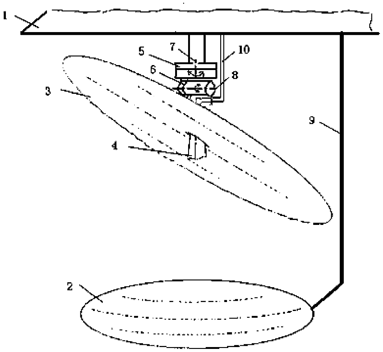
[0023] refer to figure 1 . In the embodiment described below, a wide-angle beam scanning reflector antenna includes an azimuth servo mechanism 5 and a pitch servo mechanism 6 fixed on the antenna platform 1, a feed source 4 fixedly connected to the waveguide feeder line 10, It is characterized in that the azimuth servo mechanism 5 is connected with the pitch servo mechanism 6 to form a combined two-dimensional servo mechanism, and the sputtering plate 3 is connected to the two-dimensional servo mechanism, and the feed source 4 is fixed on the sputtering plate through the waveguide flange plate of the waveguide feeder 10. The center of the plate 3 is fixed; the bottom of the sputtering plate 3 is provided with a reflective surface 2 connected by a bending structure 9 fixedly installed on the antenna platform 1, and the azimuth servo mechanism 5 drives the pitch servo mechanism 6 to drive the sputtering plate 3. The plate 3 rotates around the azimuth rotation axis 7 and the pit...


PUM


Abstract

The invention discloses a wide-angle beam scanning reflector antenna which has the advantages of low power consumption, high transmission efficiency and unlimited polarization mode. According to the technical scheme of the invention, an azimuth servo mechanism is connected with a pitch servo mechanism to form a combined two-dimensional servo mechanism; the two-dimensional servo mechanism is connected with a sputter plate (3); a feed source (4) is fixed at the center of the sputter plate through a waveguide feed line (10); a reflector (2) connected by a bent structural member (9) fixedly arranged on an antenna platform (1) is arranged below the sputter plate; the azimuth servo mechanism drives the pitch servo mechanism to drive the sputter plate to rotate around an azimuth rotation axis (7)and a pitch rotation axis (8), so as to realize limited scanning of the pitch plane of an antenna beam and wide angle scanning of the azimuth plane; after an electromagnetic wave is transmitted by the feed source to the reflector, the electromagnetic wave is reflected, defocused and projected onto the sputter plate; and after being reflected by the mirror image of the sputter plate, the electromagnetic wave is emitted.

Description

technical field [0001] The invention relates to a reflector antenna widely used in various fields such as communication, radar, microwave communication, satellite communication, tracking and remote sensing. More specifically, the present invention relates to a reflector antenna whose feed source is fixed and which realizes wide-angle scanning of azimuth beams by rotating a sputtering plate. Background technique [0002] In recent years, reflector antennas have become a mainstay in satellite communications. However, technologies such as satellite communication put forward high requirements for wide-angle scanning performance on the dual-reflector antenna, which requires the antenna to be in a large wide-angle scanning range, the radiation pattern is too distorted, the gain loss is small, and the sidelobe level fulfil requirements. Mechanically scanned reflector antennas, in particular, require careful consideration of mechanical design details. Reflective surfaces must be ...

Claims


Application Information

Patent Timeline
Patent Type & Authority Applications(China)
IPC IPC(8): H01Q3/20H01Q19/19
CPCH01Q3/20H01Q19/19
Inventor 官正涛李秀梅何海丹
Owner 10TH RES INST OF CETC
Learn More