Wear-resisting steel ball impurity removal device

A technology of wear-resistant steel and miscellaneous boxes, which is applied in the direction of cleaning methods using liquids, cleaning methods and utensils, and cleaning methods using tools, etc., which can solve problems such as inability to wash off, collision damage, and inability to remove stains, so as to reduce energy consumption. Consumption, improve protection, improve the effect of cleanliness

Inactive Publication Date: 2019-11-01
江苏首盾耐磨材料有限公司
View PDF8 Cites 3 Cited by
  • Summary
  • Abstract
  • Description
  • Claims
  • Application Information

AI Technical Summary

Problems solved by technology

[0002] At present, there are still some deficiencies in the existing wear-resistant steel ball impurity removal device, for example; It reduces the energy consumption when cleaning the surface of the sphere, reduces the efficiency of the sphere cleaning process, and the existing wear-resistant steel ball impurity removal device cannot remove the stains attached to the surface of the sphere, and small stains appear on the surface of the sphere The phenomenon that the cleaning cannot be removed reduces the cleanliness of the surface of the sphere after cleaning, and the sphere will be damaged by collision when the sphere is decontaminated, which weakens the protective effect on the sphere during decontamination.

Method used


Image

  • Wear-resisting steel ball impurity removal device
  • Wear-resisting steel ball impurity removal device
  • Wear-resisting steel ball impurity removal device

Examples


Embodiment Construction

[0020] The following will clearly and completely describe the technical solutions in the embodiments of the present invention with reference to the accompanying drawings in the embodiments of the present invention. Obviously, the described embodiments are only some, not all, embodiments of the present invention.

[0021] In describing the present invention, it should be understood that the terms "upper", "lower", "front", "rear", "left", "right", "top", "bottom", "inner", " The orientation or positional relationship indicated by "outside", etc. is based on the orientation or positional relationship shown in the drawings, and is only for the convenience of describing the present invention and simplifying the description, rather than indicating or implying that the referred device or element must have a specific orientation, so as to Specific orientation configurations and operations, therefore, are not to be construed as limitations on the invention.

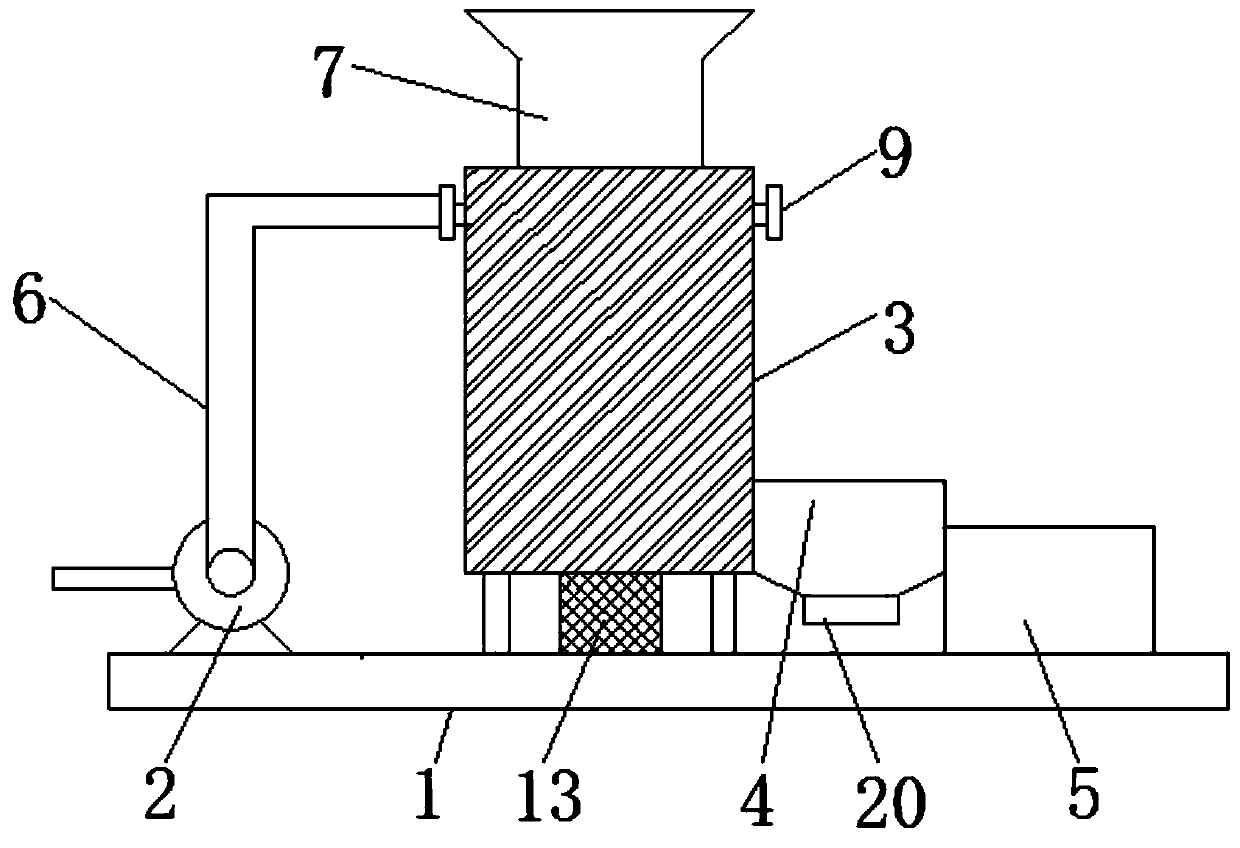
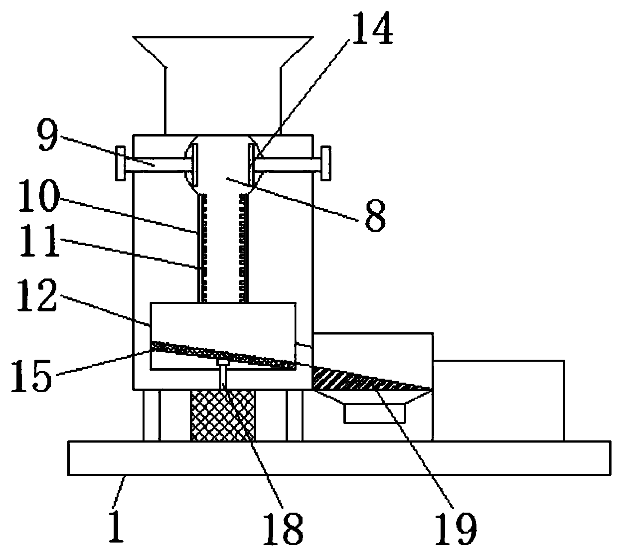
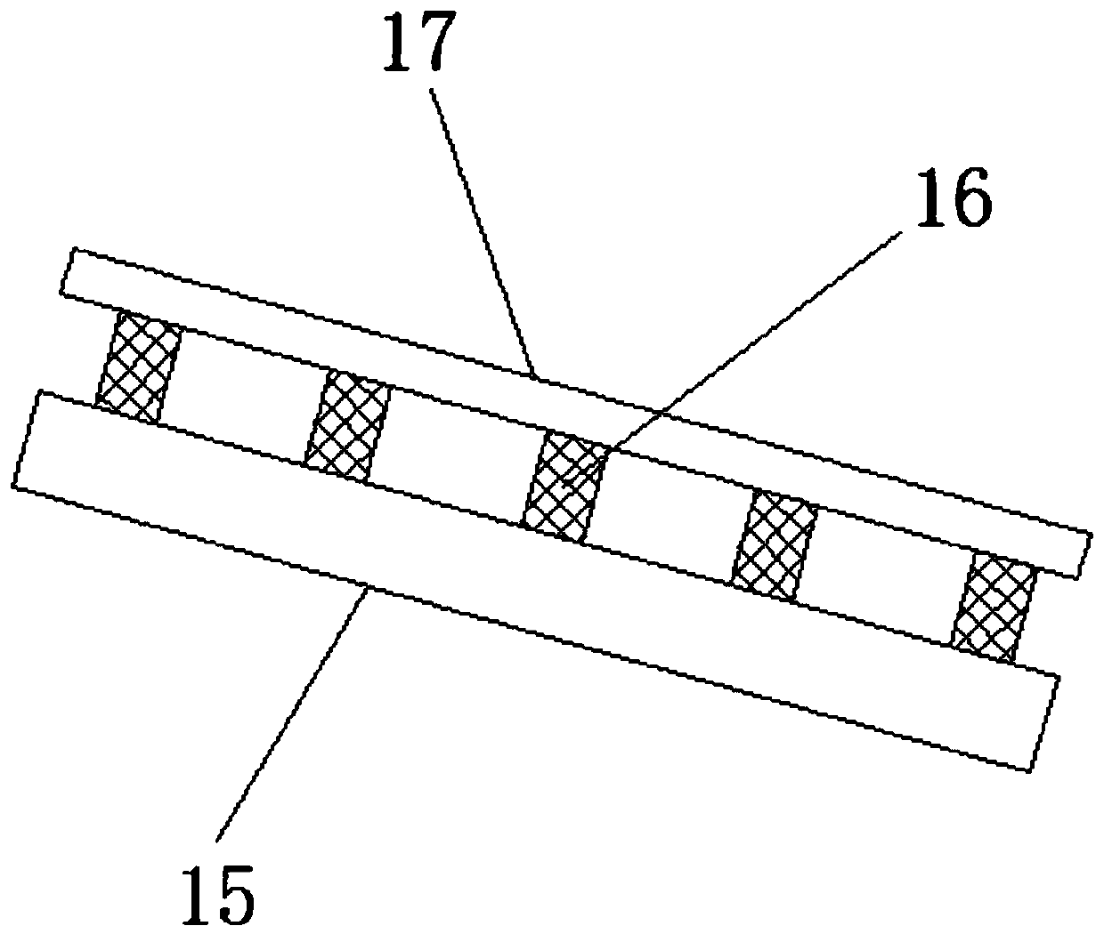
[0022] see Figure 1-3 ,...


PUM


Abstract

The invention discloses a wear-resisting steel ball impurity removal device. The device structurally comprises a base. A liquid suction pump, an impurity removal box, a filter box and a recycling boxare arranged on the base, the liquid suction pump is fixedly connected to the left side of the upper surface of the base, the impurity removal box is fixedly connected to the middle of the upper surface of the base, the filter box is fixedly connected to the upper surface of the base, the recycling box is fixedly connected to the right side of the upper surface of the base, a water conveying pipeis arranged on the liquid suction pump, a ball placement hopper, an impurity removal groove, water receiving pipes, a guiding pipe, a brush plate, a vibrating box and a drive motor are arranged on theimpurity removal box, the ball placement hopper is located at the upper end of the impurity removal box, the impurity removal groove is located at the lower end of the ball placement hopper and located inside the impurity removal box, and the water receiving pipes are fixedly connected to the left and right sides of the upper portion of the impurity removal box. The phenomenon that small stains are attached to the surface of the ball and cannot be cleaned away is avoided, and the cleanness of the cleaned ball surface is improved.

Description

technical field [0001] The invention relates to the technical field of impurity removal devices, in particular to a wear-resistant steel ball impurity removal device. Background technique [0002] At present, there are still some deficiencies in the existing wear-resistant steel ball impurity removal device, for example; It reduces the energy consumption when cleaning the surface of the sphere, reduces the efficiency of the sphere cleaning process, and the existing wear-resistant steel ball impurity removal device cannot remove the stains attached to the surface of the sphere, and small stains appear on the surface of the sphere The phenomenon that it cannot be cleaned off reduces the cleanliness of the surface of the sphere after cleaning, and the sphere will be damaged by collision when the sphere is decontaminated, which weakens the protective effect on the sphere during decontamination. Contents of the invention [0003] The object of the present invention is to provi...

Claims


Application Information

Patent Timeline
Patent Type & Authority Applications(China)
IPC IPC(8): B08B7/02B08B1/02B08B3/02B08B3/14B08B13/00
CPCB08B1/002B08B1/02B08B3/022B08B3/14B08B7/02B08B13/00
Inventor 单东峰
Owner 江苏首盾耐磨材料有限公司
Why Eureka
Try Eureka