

Forecast system of sulfur dioxide in heating furnace flue gas, and forecast method
A sulfur dioxide and forecasting system technology, applied in the direction of measuring devices, instruments, scientific instruments, etc., to achieve ultra-low emissions and reduce desulfurization costs
- Summary
- Abstract
- Description
- Claims
- Application Information
AI Technical Summary
Problems solved by technology
Method used
Image

Examples
Embodiment Construction
[0026] The specific embodiment of the present invention will be described in further detail by describing the embodiments below with reference to the accompanying drawings, the purpose is to help those skilled in the art to have a more complete, accurate and in-depth understanding of the concept and technical solutions of the present invention, and contribute to its implementation. It should be noted that the orientation or positional relationship indicated by the terms "upper", "lower", "front", "rear", "left", "right", "vertical", "inner" and "outer" are Based on the orientation or positional relationship shown in the drawings, it is only for the convenience of describing the present invention and simplifying the description, and does not indicate or imply that the referred device or element must have a specific orientation, be constructed and operated in a specific orientation, and therefore cannot be understood for limitation of the invention.
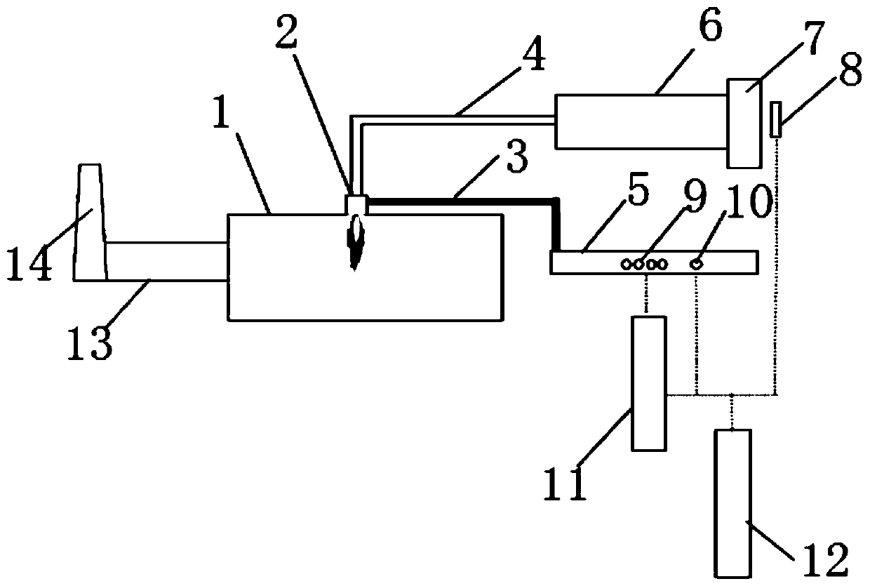
[0027] Such as figure 1 S...
PUM
 Abstract
Description
Claims
Application Information