
Self-supplied hydrogen fuel cell system and working method thereof

a hydrogen fuel cell and self-supplied technology, applied in the direction of fuel cells, reactant parameter control, electrical apparatus, etc., can solve the problems of hydrogen source, not only achieving zero-emission fuel cells, but also solving the problem of hydrogen sources, given no overall scheme of fuel cells, etc., to achieve ultra-low emission, avoid nox and particulate matter generation, and enhance work capacity

Inactive Publication Date: 2018-06-05
BEIJING UNIV OF CIVIL ENG & ARCHITECTURE
View PDF9 Cites 0 Cited by
  • Summary
  • Abstract
  • Description
  • Claims
  • Application Information

AI Technical Summary

Benefits of technology

The invention is about making diesel fuel have a good reaction with hot water steam and oxygen to produce carbon dioxide and hydrogen. Hydrogen is a fuel needed for a fuel cell, which can generate electric energy with oxygen in the air. Carbon dioxide enters the catalytic burner for combustion and is released into the air, resulting in ultra-low emissions. This invention achieves ultra-low emission in diesel engines, improves work capacity, and avoids the generation of nitrogen oxides and particulate matters. Additionally, it solves the issue of power supply for diesel vehicles and achieves ultra-low emission of diesel engines.

Problems solved by technology

However, the active chemical property of hydrogen makes it a problem for hydrogen storage.
With the technology of auto-thermal conversion of diesel designed in the Invention, it can not only achieve zero-emission of the fuel cell, but also solve the problem of hydrogen source.
Some reference patents (CN101142016B and U.S. Pat. No. 8,349,288) have provided a device and a method for homogeneous conversion of oil and oxygen as well as an approach and a method for auto-thermal conversion of methane, but they have given no overall scheme with fuel cell.
With inadequate design for self-supply of hydrogen for fuel cell, the practical applicability needs to be further studied.

Method used


Image

  • Self-supplied hydrogen fuel cell system and working method thereof
  • Self-supplied hydrogen fuel cell system and working method thereof

Examples


Embodiment Construction

[0015]The Invention is further described in combination with the FIGURE as follows:

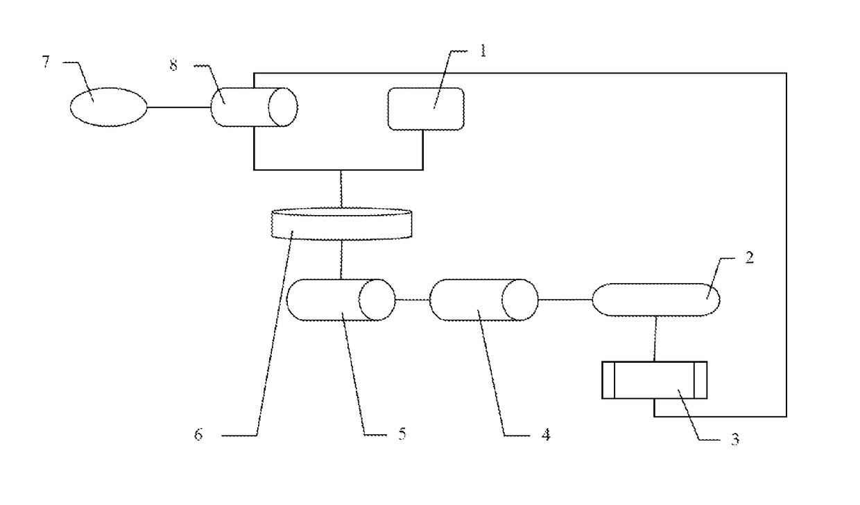
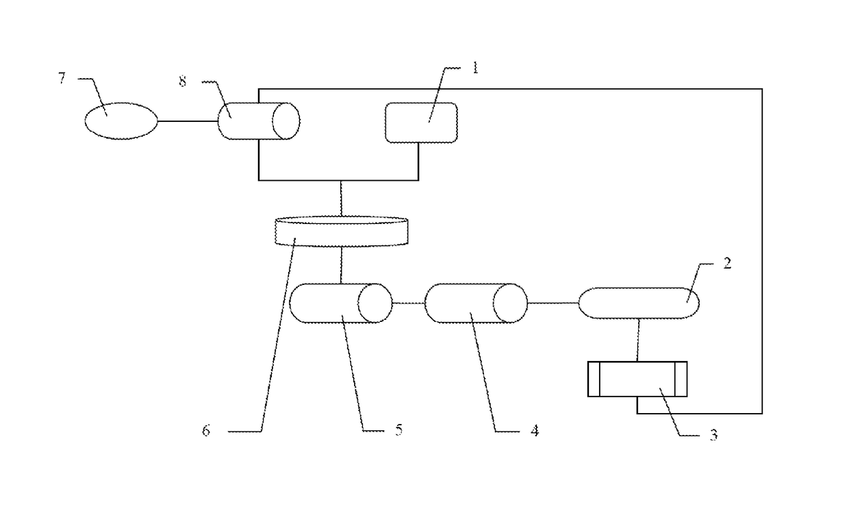
[0016]With reference to the FIGURE, the self-supplied hydrogen fuel cell system of the Invention comprises a diesel tank 1, a gas separator 2, a fuel cell 3, a low-temperature separation reactor 4, a high-temperature separation reactor 5, an auto-thermal reformer 6, a water tank 7 and a catalytic burner 8;

[0017]wherein, the diesel tank 1 and the catalytic burner 8 are respectively connected to the auto-thermal reformer 6 through a pipeline; the catalytic burner 8 is respectively connected to the water tank 7 and the fuel cell 3; the auto-thermal reformer 6, the high-temperature separation reactor 5, the low-temperature separation reactor 4, the gas separator 2 and the fuel cell 3 are connected in series;

[0018]wherein, the outlet pipe of the water tank 7 is connected to the water inlet of the catalytic burner 8; the steam outlet of the catalytic burner 8 is connected to the oil / steam inlet of the auto-...


PUM

PropertyMeasurementUnit
temperatureaaaaaaaaaa

Abstract

The Invention discloses a self-supplied hydrogen fuel cell system and a working method thereof, the system comprising a diesel tank, a gas separator, a fuel cell, a low-temperature separation reactor, a high-temperature separation reactor, an auto-thermal reformer, a water tank and a catalytic burner; With the high-temperature separation reactor, the low-temperature separation reactor and the auto-thermal reformer, diesel is cracked into H2 and CO; as the fuel for the fuel cell, H2 may react with O2 in the air and generate electric energy; the unreacted H2 and CO enter into the catalytic burner for combustion, ensuring that the water is heated; thus, it not only provides H2 to the fuel cell, but also provides high-temperature water to the auto-thermal converter to produce H2; electric energy can be generated without burning diesel; since no NOx or particulate matters but CO2 is generated, the goal of ultra-low emission is achieved.

Description

CROSS REFERENCE TO RELATED APPLICATIONS[0001]The present application is a Continuation Application of PCT application No. PCT / CN2016 / 079092 filed on Apr. 12, 2016, which claims the benefits of Chinese Patent Application No. 201510383244.7 filed on Jul. 2, 2015, the contents of which are hereby incorporated by reference.FIELD OF THE INVENTION[0002]The Invention relates to the field of fuel cell technology and particularly to a self-supplied hydrogen fuel cell system and a working method thereof.BACKGROUND OF THE INVENTION[0003]As a new energy source for vehicles, fuel cell is becoming a research hotspot, and the related technology of hydrogen supply is also becoming a research emphasis. With the advantages of high efficiency, large energy density, low noise and non-pollution, proton exchange membrane fuel cell is regarded as the next generation of power unit for vehicles which is mostly to replace internal combustion engine. Hydrogen, the fuel for proton exchange membrane fuel cell, ...

Claims


Application Information

Patent Timeline
Patent Type & Authority Patents(United States)
IPC IPC(8): H01M8/0612H01M8/0668H01M8/04082H01M8/22H01M8/06
CPCH01M8/0618H01M8/04201H01M8/22H01M8/0668H01M8/06H01M8/04022H01M8/0606Y02E60/50
Inventor LIU, YONGFENGCHEN, HONGBINGQIN, JIANJUNPEI, PUCHENGYAO, SHENGZHUO
Owner BEIJING UNIV OF CIVIL ENG & ARCHITECTURE
Features
  • Generate Ideas
  • Intellectual Property
  • Life Sciences
  • Materials
  • Tech Scout
  • Unparalleled Data Quality
  • Higher Quality Content
  • 60% Fewer Hallucinations
Learn More