Aircraft laser receiving equipment

A laser receiving and aircraft technology, applied in the laser field, can solve the problems of poor stability signal detection accuracy, ground laser receiving terminal damage, high maintenance cost, etc., to improve the ability to resist external noise interference, suppress background noise, and effectively resist Effects of Particle Irradiation

Active Publication Date: 2019-11-01
北立传感器技术(武汉)有限公司
View PDF5 Cites 0 Cited by
  • Summary
  • Abstract
  • Description
  • Claims
  • Application Information

AI Technical Summary

Problems solved by technology

[0002] Satellite surveying and mapping technology is changing with each passing day, and the resolution of satellite images has broken through the sub-meter level. However, surveying and mapping products used in resource investigation, environmental monitoring, polar surveying and mapping, disaster emergency response and other industries are limited by elevation accuracy.
In order to make up for the lack of elevation accuracy of domestic three-dimensional surveying and mapping products, some experts and scholars have proposed a new idea of ​​combining a spaceborne laser altimeter and a three-dimensional surveying camera on the same platform for composite surveying and mapping to improve the high precision of satellite uncontrolled surveying. The laser receiving terminals are all open settings, which are easy to be damaged in the outdoor environment, and the maintenance cost is relatively high, especially in harsh environments, such as sand, stone, rain and snow, which will cause irreparable damage to the ground laser receiving terminal
In addition, when carrying out laser height measurement outdoors, due to the characteristics of small laser energy emitted by the laser, short pulse time, and long transmission distance, the current receiving terminal has poor reception stability and signal detection accuracy, resulting in low equipment reliability. Difference

Method used


Image

  • Aircraft laser receiving equipment
  • Aircraft laser receiving equipment
  • Aircraft laser receiving equipment

Examples


Embodiment Construction

[0041] The principles and features of the present invention are described below in conjunction with the accompanying drawings, and the examples given are only used to explain the present invention, and are not intended to limit the scope of the present invention.

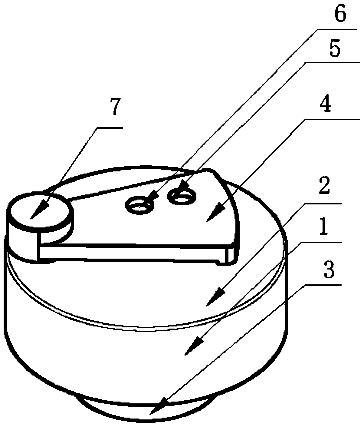
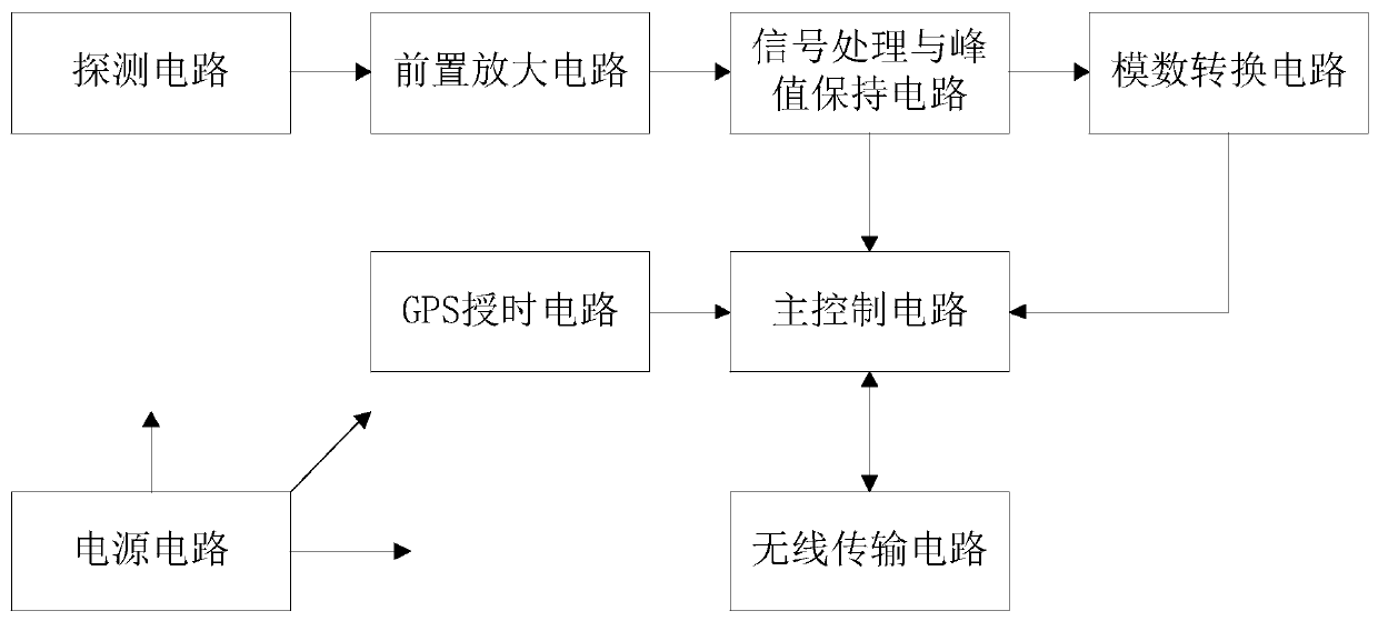
[0042] Such as figure 1 with figure 2 As shown, an aircraft laser receiving device includes a hollow terminal body 1, an upper cover 2 and a lower cover 3, the upper cover 2 and the lower cover 3 are respectively arranged at the upper and lower ends of the terminal body 1, and form Airtight cavity, the upper cover 2 is provided with a laser through hole for the laser to pass through, and the upper cover 2 is provided with a rotating piece 4, and the rotating piece 4 can be rotated to open or close the laser through hole. hole, the airtight cavity is provided with a detection circuit, a preamplifier circuit, a signal processing and peak hold circuit, an analog-to-digital conversion circuit, a main control circuit a...


PUM


Abstract

The invention relates to aircraft laser receiving equipment. The equipment includes a terminal body, an upper cover and a lower cover. The upper cover and the lower cover are respectively disposed atan upper end and a lower end of the terminal body and form a closed cavity. Laser through holes are disposed on the upper cover. A detection circuit, a preamplifier circuit, a signal processing and peak value hold circuit, an analog-to-digital conversion circuit, a main control circuit and a power supply circuit are disposed in the closed cavity. The detection circuit, the preamplifier circuit andthe signal processing and peak value hold circuit are sequentially and electrically connected. The signal processing and peak value hold circuit are electrically connected with the analog-to-digitalconversion circuit and the main control circuit respectively. The analog-to-digital conversion circuit is electrically connected with the main control circuit. According to the equipment, the laser through holes can be opened or closed, irreparable damage caused by the sand stone, rain and snow weathers on an inside in long-term idling is prevented, lasers can be received and detected in real timethrough the detection circuit, real-time laser capturing and detection are facilitated, long-distance measurement and determination are effectively realized, and detection accuracy is higher.

Description

technical field [0001] The invention relates to the field of laser technology, in particular to an aircraft laser receiving device. Background technique [0002] Satellite surveying and mapping technology is changing with each passing day, and the resolution of satellite images has broken through the sub-meter level. However, surveying and mapping products used in resource investigation, environmental monitoring, polar surveying and mapping, disaster emergency response and other industries are limited by elevation accuracy. In order to make up for the lack of elevation accuracy of domestic three-dimensional surveying and mapping products, some experts and scholars have proposed a new idea of ​​combining a spaceborne laser altimeter and a three-dimensional surveying camera on the same platform for composite surveying and mapping to improve the high precision of satellite uncontrolled surveying. The laser receiving terminals are all open settings, which are easy to be damaged ...

Claims


Application Information

Patent Timeline
IPC IPC(8): G01S7/486G01S7/481G01S7/495G01S7/497G01S17/88G01C15/00G05B19/042
CPCG01S7/486G01S7/4861G01S7/4816G01S7/495G01S7/497G01S17/88G01C15/00G05B19/0423
Inventor 李龙
Owner 北立传感器技术(武汉)有限公司
Why Eureka
Try Eureka