Direct current power supply device

A DC power supply and voltage technology, applied in output power conversion devices, electrical components, high-efficiency power electronic conversion and other directions, can solve problems such as difficult to deal with, PFC circuit turn-on, turn-off switching control lag, etc., to achieve efficiency improvement, easy and rapid response

Pending Publication Date: 2019-11-01
MITSUMI ELECTRIC CO LTD
View PDF2 Cites 0 Cited by
  • Summary
  • Abstract
  • Description
  • Claims
  • Application Information

AI Technical Summary

Problems solved by technology

In addition, in the switching power supply device of Patent Document 1, there is no hysteresis in turning on and off the control circuit, so when the magnitude of the load is in the vicinity of the switching level of turning on and off the control circuit, there may be The problem of the oscillation phenomenon that causes the control circuit to be turned on and off repeatedly
[0008] On the other hand, in Patent Document 2, it is described that a control circuit and a PFC circuit for driving a switching unit connected to a primary coil of a transformer are provided, a load state detection circuit and a load state detection circuit that detects and outputs light A period setting circuit that inputs a signal of the load state and outputs a signal indicating that a preset time has elapsed, and a PFC on that controls the ON and OFF of the PFC circuit based on the signal output from the period setting circuit In a switching power supply device with an off-switching circuit, a Schmitt trigger circuit is used in the PFC on-off switching circuit, so that the on-off switching control of the PFC circuit has a hysteresis
[0009] However, in the switching power supply device described in Patent Document 2, since the output current value when the PFC circuit is switched from on to off, the output current value or the switching load factor (ratio to the rated load) and the PFC circuit cannot be independently set. The output current value or load factor when the circuit is switched from off to on, so there is a problem that it is difficult to respond quickly when there is a new efficiency limit

Method used


Image

  • Direct current power supply device
  • Direct current power supply device
  • Direct current power supply device

Examples


Embodiment Construction

[0035] Hereinafter, preferred embodiments of the present invention will be described with reference to the drawings.

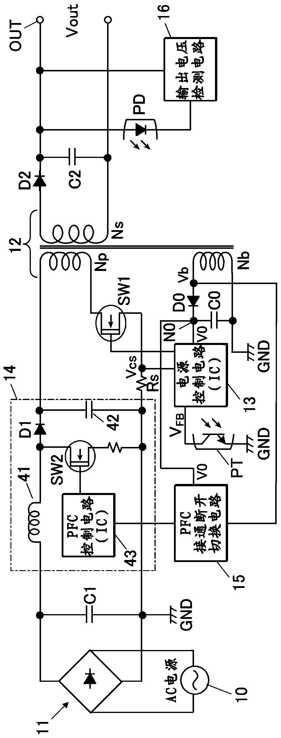
[0036] figure 1 It is a circuit configuration diagram showing an embodiment of an AC-DC converter as a switching power supply device to which the present invention is applied.

[0037] The AC-DC converter of this embodiment includes: a diode bridge circuit 11 for rectifying an alternating voltage (AC) from an AC power supply 10; Transformer 12 for voltage conversion of side coil Np, secondary side coil Ns, and auxiliary coil Nb, switching transistor SW1 connected in series with primary side coil Np of transformer 12, switching transistor SW1 for turning on and off A power supply control circuit 13, a power factor improvement circuit (PFC circuit) 14 provided between the diode bridge circuit 11 and the transformer 12, and a circuit for setting the power factor improvement circuit 14 to an operating state (on) or a non-operating state (off) The PFC on-off swit...


PUM


Abstract

In a DC power supply device having a power factor improving circuit, the oscillation phenomenon that causes the circuit to repeatedly turn on and off when the power factor improvement control circuitoperates can be prevented, and the power factor improvement control circuit is turned off according to the set value to improve the efficiency of light load. In the DC power supply device having the power factor improving circuit (14), the first control circuit (13) and the second control circuit (43) are configured to operate with a voltage induced by an auxiliary coil of a transformer (12). An on / off switching circuit (15) of the second control circuit is provided between one terminal of the auxiliary coil and the power terminal of the second control circuit. The on / off switching circuitincludes a detection unit (51) for detecting a light load state based on a voltage induced by an auxiliary coil, an operation control unit (52) that stops the operation of the second control circuitwhen a light load state is detected by the detection unit, and a hysteresis imparting unit (53) that applies a hysteresis characteristic to the operation of the load state detecting unit.

Description

technical field [0001] The present invention relates to a DC power supply device equipped with a transformer for voltage conversion, and particularly relates to an effective technique for use in a switch-controlled isolated DC power supply device having a power factor improvement circuit. Background technique [0002] In the DC power supply device, there is an isolated AC-DC converter. The isolated AC-DC converter consists of a diode bridge circuit that rectifies the AC power supply, and the DC voltage rectified by the circuit is stepped down and converted into the desired voltage. Potential direct voltage DC-DC converter etc. constitute. As an isolated AC-DC converter, for example, a switching power supply device is known that uses a PWM (Pulse Width Modulation) control method, a PFM (Pulse Frequency Modulation) control method, etc. to turn on and off a transformer for driving and voltage conversion. The switching elements connected in series to the primary side coil contr...

Claims


Application Information

Patent Timeline
Patent Type & Authority Applications(China)
IPC IPC(8): H02M3/28H02M1/42
CPCH02M3/28H02M1/4258Y02B70/10
Inventor 小室阳介
Owner MITSUMI ELECTRIC CO LTD
Why Eureka
Try Eureka