Underground engineering radon gas adsorption treatment apparatus

A technology of adsorption treatment and underground engineering, applied in gas treatment, nuclear engineering, membrane technology, etc., can solve the problems of secondary pollution, easy desorption, easy saturation, etc., to reduce the amount of use, reduce the resistance of activated carbon, and increase the service life Effect

Inactive Publication Date: 2019-11-05
NANHUA UNIV
View PDF6 Cites 4 Cited by
  • Summary
  • Abstract
  • Description
  • Claims
  • Application Information

AI Technical Summary

Problems solved by technology

[0002] At present, the adsorption of radon in the air of underground engineering generally adopts the physical adsorption method, and the unit of radon concentration in the air is Bq/m 3 , which represents the number of radon atoms that undergo radioactive decay in one cubic meter of air in one second, and there are about 2.68×10 in one cubic meter of air 25 molecules, so even the higher radon concentration of 10000 Bq/m 3 Radon-containing air, the ratio of the number of radon atoms to the number of air molecules is also very small, and the air radon concentration in the living environment is reduced to the prescribed action level of 200-400 Bq/m 3 , a large amount of activated carbon is required to effectively capture and adsorb radon atoms and achieve the expected treatment effect. In addition, activated carbon can also adsorb gases such as nitrogen in addition to

Method used


Image

  • Underground engineering radon gas adsorption treatment apparatus
  • Underground engineering radon gas adsorption treatment apparatus
  • Underground engineering radon gas adsorption treatment apparatus

Examples


Embodiment 1

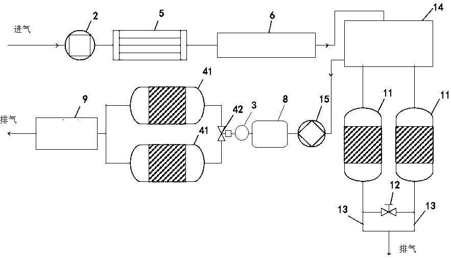
[0026] like figure 1 The shown underground engineering radon adsorption treatment device includes a plurality of activated carbon beds 11 for adsorbing radon or desorbing radon, air compressor 2 that will contain radon air from the source into the activated carbon bed, and the activated carbon bed 11 is at least two A throttling valve 12 is installed between adjacent activated carbon beds, so that the air flow circulates between adjacent activated carbon beds; an exhaust pipe 13 is connected to the connecting pipe between each end of the throttle valve 12 and the activated carbon bed 11, including After the radon air is compressed by the air compressor 2, it is sent into one or more activated carbon beds 11 through the electromagnetic valve 14 for radon adsorption. After that, part of the air coming out of the activated carbon beds 11 for radon adsorption is discharged through the exhaust pipe 13. (The air adsorbed by the activated carbon bed is clean air), the other part ente...


PUM


Abstract

The invention relates to the technical field of gas adsorption, and discloses an underground engineering radon gas adsorption treatment apparatus, which comprises active carbon beds for radon adsorption or radon desorption, and an air compressor for feeding radon-containing air into the active carbon bed, at least the two active carbon beds are arranged, a throttle valve is arranged between the adjacent active carbon beds, and gas discharge pipelines are connected to the connecting pipelines between each end portion of the throttle valve and the active carbon beds. According to the present invention, after radon-containing air is compressed, the compressed radon-containing air is fed into one or a plurality of the active carbon beds through the electromagnetic valve so as to be subjected to radon gas adsorption; part of the air discharged from the active carbon bed performing radon gas adsorption is discharged through the gas discharge pipeline, and another part enters the adjacent oneor a plurality of the active carbon beds through the throttle valve so as to be subjected to radon desorption; the gas discharged from the active carbon bed performing radon desorption is fed into the compression device through the electromagnetic valve so as to be pressurized, and the other end of the compression device is provided with the active carbon bed used for pressurizing storage and capable of decaying the radon gas; and the gas is subjected to radon decaying by the active carbon bed used for pressurizing storage, and then is directly discharged to the outside world.

Description

technical field [0001] The invention belongs to the technical field of gas adsorption, and in particular relates to an underground engineering radon gas adsorption treatment device. Background technique [0002] At present, the adsorption of radon in the air of underground engineering generally adopts the physical adsorption method, and the unit of radon concentration in the air is Bq / m 3 , which represents the number of radon atoms that undergo radioactive decay in one cubic meter of air in one second, and there are about 2.68×10 in one cubic meter of air 25 molecules, so even the higher radon concentration of 10000 Bq / m 3 Radon-containing air, the ratio of the number of radon atoms to the number of air molecules is also very small, and the air radon concentration in the living environment is reduced to the prescribed action level of 200-400 Bq / m 3 , a large amount of activated carbon is required to effectively capture and adsorb radon atoms and achieve the expected treat...

Claims


Application Information

Patent Timeline
IPC IPC(8): B01D53/04G21F9/02
CPCB01D53/04B01D53/0454B01D2257/10B01D2259/40013B01D2259/40028G21F9/02
Inventor 冯旭肖德涛龙慧佳丘寿康
Owner NANHUA UNIV
Why Eureka
Try Eureka