A fixing device for ammunition grain forming process

A forming processing and fixing device technology, applied in the direction of the chuck, etc., can solve the problems of lower machining accuracy and lower production efficiency of machine tools, and achieve the effects of high operation efficiency, fast response speed and simple action

Active Publication Date: 2020-08-28
SHENYANG INST OF AUTOMATION - CHINESE ACAD OF SCI
View PDF7 Cites 0 Cited by
  • Summary
  • Abstract
  • Description
  • Claims
  • Application Information

AI Technical Summary

Problems solved by technology

When the existing chuck is working, the claws need to be manually adjusted to clamp and loosen the workpiece, which reduces the production efficiency and the machining accuracy of the machine tool

Method used


Image

  • A fixing device for ammunition grain forming process
  • A fixing device for ammunition grain forming process
  • A fixing device for ammunition grain forming process

Examples


Embodiment Construction

[0030] The present invention will be described in further detail below in conjunction with the accompanying drawings.

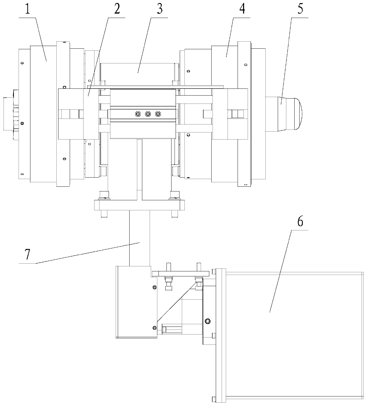
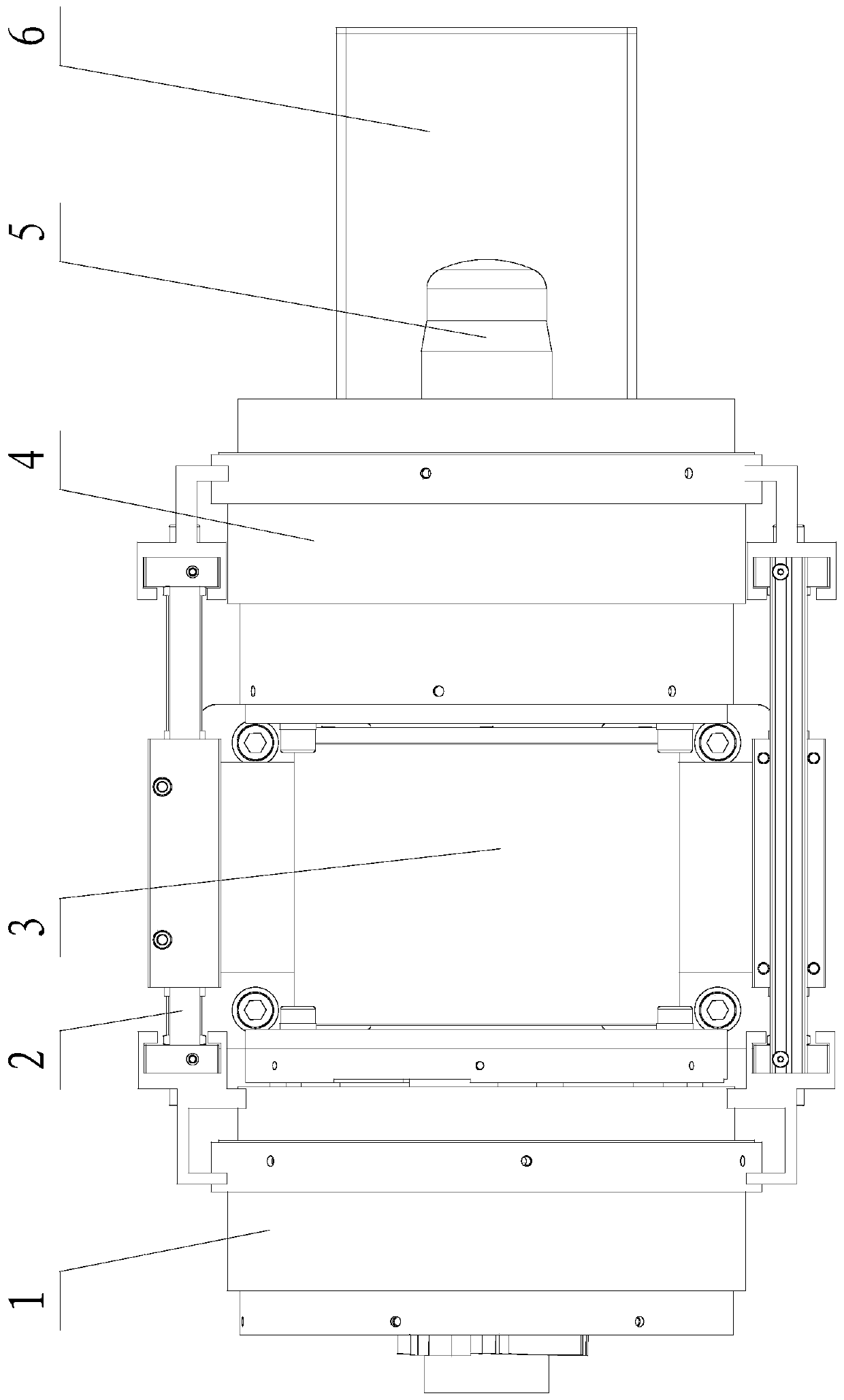
[0031] Such as Figure 1-9 As shown, the present invention includes a jaw assembly, a jaw driving mechanism, a chuck bearing seat 3 and a main shaft rotation driving mechanism 6, wherein the chuck bearing seat 3 is installed on a workbench (the workbench in this embodiment is formed and processed by ammunition cartridges) On the platform), the chuck bearing seat 3 has a through hole and a built-in main shaft, and the main shaft is rotatably connected with the chuck bearing seat 3 through a bearing; The main shaft is connected to the output end of the main shaft rotation driving mechanism 6, and is driven to rotate by the main shaft rotation driving mechanism 6, and a jaw assembly that rotates with the main shaft is installed on the main shaft. The main shaft rotation driving mechanism 6 of the present embodiment includes a driving motor, a driving wheel A, a...


PUM


Abstract

The invention relates to a fixing device for ammunition grain shaping. A chuck bearing seat is mounted on a working table, a main shaft is rotatably mounted insides, the main shaft is connected with the output end of a main shaft rotating driving mechanism, and the main shaft is provided with a clamping jaw assembly rotating along with the main shaft; one side of a fixed disc mechanism is mountedon the main shaft, the other side of the fixed disc mechanism is provided with a guide body, a push plate mechanism is contained inside the fixed disc mechanism, a push plate is connected with the output end of a clamping jaw drive mechanism mounted on the chuck bearing seat and is driven by the clamping jaw drive mechanism to do reciprocating motion in the axial direction of the main shaft, and awedge-mounted push block is mounted on the push plate; and one end of a sliding block is located in the guide body in a relatively movable manner, the other end of the sliding block is a clamping jaw, the clamping jaw is provided with a spring for resetting the sliding block, and the two ends of the spring abut against the clamping jaw and the guide body. By means of the fixing device, quick andautonomous clamping and releasing are achieved in the ammunition grain shaping process, additional disturbance power cannot be generated to equipment in the forming process, and original postures cannot be changed.

Description

technical field [0001] The invention relates to a chuck device, in particular to a fixing device for forming and processing ammunition grain columns. Background technique [0002] The chuck is a mechanical device used to clamp the workpiece on the machine tool. It uses the radial movement of the movable jaws evenly distributed on the chuck body to clamp and position the workpiece. The chuck is generally composed of three parts: the chuck body, the movable jaw and the jaw driving mechanism. When the existing chuck is working, the claws need to be manually adjusted to clamp and loosen the workpiece, which reduces the production efficiency and the machining accuracy of the machine tool. In order to enable the chuck to quickly and autonomously clamp and loosen the workpiece, and improve work efficiency and precision, a new chuck device is needed. Contents of the invention [0003] In order to solve the above-mentioned problems existing in the existing chuck and meet the prod...

Claims


Application Information

Patent Timeline
Patent Type & Authority Patents(China)
IPC IPC(8): B23B31/16B23B31/30
CPCB23B31/16B23B31/30
Inventor 张延利白鑫林王军义徐志刚何涛赵志亮李广振李东阳
Owner SHENYANG INST OF AUTOMATION - CHINESE ACAD OF SCI
Why Eureka
Try Eureka