
Electronic detonator control chip slitting equipment

A technology of controlling chips and electronic detonators, applied in metal processing, etc., can solve the problems of low production efficiency, low processing adaptability, high equipment cost, etc., achieve high production efficiency, low equipment cost, and reduce tool change time.

Inactive Publication Date: 2019-11-05
永泰山水生态农场
View PDF8 Cites 2 Cited by
  • Summary
  • Abstract
  • Description
  • Claims
  • Application Information

AI Technical Summary

Problems solved by technology

[0003] Technical problem: At present, the slitting devices for small chips are mainly CNC knife-feeding type and stamping and shearing type. The former has high equipment cost and low production efficiency, and the latter needs to be equipped with specific tools for each different chip. Processing low adaptability

Method used


Image

  • Electronic detonator control chip slitting equipment
  • Electronic detonator control chip slitting equipment
  • Electronic detonator control chip slitting equipment

Examples


Embodiment Construction

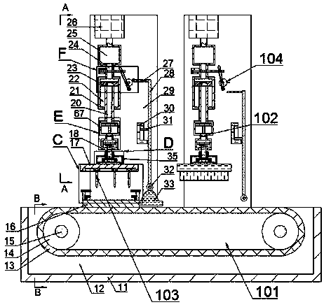
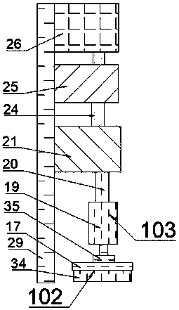
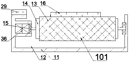
[0022] Combine below Figure 1 to Figure 7 The present invention is described in detail, and for convenience of description, the orientations mentioned below are now stipulated as follows: figure 1 The up, down, left, right, front and back directions of the projection relationship itself are the same.

[0023] The present invention relates to an electronic detonator control chip slitting device, which is mainly used for chip slitting. The present invention will be further described below in conjunction with the accompanying drawings of the present invention:

[0024]An electronic detonator control chip slitting device according to the present invention includes a delivery box 11, and the delivery box 11 is provided with a delivery cavity 12 with an opening facing upwards, and the delivery cavity 12 is provided with a delivery box for delivering the control chip. Device 101, two left and right symmetrical fixed plates 29 are fixedly connected to the upper end surface of the re...


PUM


Abstract

The invention discloses electronic detonator control chip slitting equipment. The electronic detonator control chip slitting equipment comprises a conveying box; the conveying box is internally provided with a conveying cavity with an upward opening; the conveying cavity is internally provided with a conveying device for conveying control chips; the upper end surface of the rear side of the conveying cavity is fixedly connected with two left and right symmetrical fixing plates; the front side end faces of the fixing plates on the left side and the right side are each provided with one power device; the front side end faces of the fixing plates are provided with quick-release cutters which are positioned on the lower sides of the power devices and used for cutting the chips; trigger devicespositioned on the right sides of the power devices are arranged on the front side end faces of the fixing plates; and the trigger devices are used for triggering the power devices to move downwards.According to the electronic detonator control chip slitting equipment, the cutters can be quickly replaced by a quick-release cutter set, the quick-release cutter set can adapt to processing of different chips by adjusting the distance between the cutters in a sliding mode, so that the electronic detonator control chip slitting equipment is strong in processing applicability, high in production efficiency and low in equipment cost.

Description

technical field [0001] The invention relates to the technical field of chip slitting, in particular to an electronic detonator control chip slitting device. Background technique [0002] Electronic detonator, that is, an electric detonator that uses an electronic control chip to control the detonation process. The electronic control chip is placed inside the digital electronic detonator, which has the functions of detonator detonation delay time control and detonation energy control. The detonator identity information code and detonation password are built-in It is a special circuit module that can test its own function, performance and the electrical performance of the detonator's ignition element, and can communicate with the detonation controller and other external control equipment, and the control chip of the electronic detonator is small. Currently, it is aimed at the analysis of small chips The cutting devices are mainly CNC knife-feeding type and stamping and shearin...

Claims


Application Information

Patent Timeline
Patent Type & Authority Applications(China)
IPC IPC(8): B26D1/08B26D7/26B26D5/12
CPCB26D1/08B26D5/12B26D7/2614B26D7/2628
Inventor 陈昶
Owner 永泰山水生态农场
Learn More