
Polystyrene light guide plate

A polystyrene and light guide plate technology, applied in the field of light guide plates, can solve problems such as light guide plate fixation, light guide plate thickness, light guide plate cutting size deviation, etc., to achieve a clean working environment, better light guide effect, and cutting smooth process effect

Active Publication Date: 2019-11-05
河源鸿智电子技术有限公司
View PDF5 Cites 0 Cited by
  • Summary
  • Abstract
  • Description
  • Claims
  • Application Information

AI Technical Summary

Problems solved by technology

[0003] At present, the light guide plate is used on the liquid crystal display screen of various digital products and various light box advertisements. The existing light guide plate needs to be cut according to the size required by the product after production, but when the existing cutting device is in use, Usually, the light guide plate is directly placed on the horizontal platform for cutting. It is difficult to fix the light guide plate during the cutting process, which can easily cause deviations in the cutting size of the light guide plate, resulting in scrapping and unusability. At the same time, dust and Unpleasant odorous gas floods the working environment, making the working environment poor. The light guide plates on the market need to be laminated with multi-layer structures to improve the light guiding effect, making the light guide plates thicker and reducing their practicability. , proposed a polystyrene light guide plate to solve the above problems

Method used


Image

  • Polystyrene light guide plate
  • Polystyrene light guide plate
  • Polystyrene light guide plate

Examples


Embodiment Construction

[0025] In order to make the technical means, creative features, goals and effects achieved by the present invention easy to understand, the present invention will be further described below in conjunction with specific embodiments.

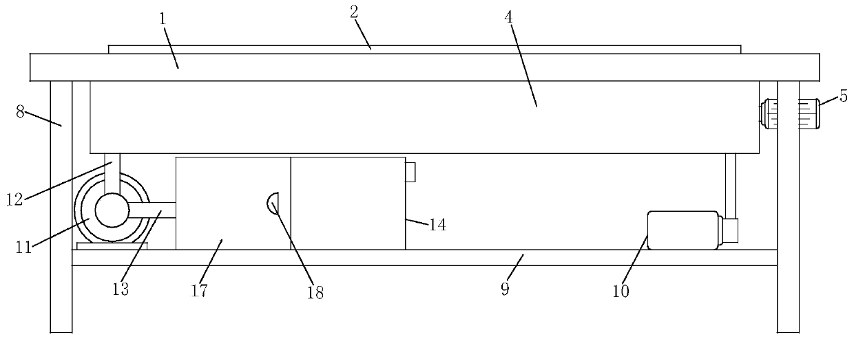
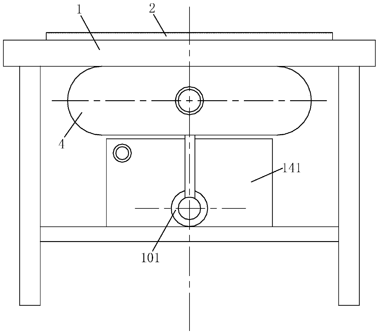
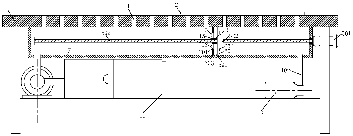
[0026] Such as Figure 1-Figure 6 As shown, a polystyrene light guide plate according to the present invention includes a cutting table 1, a light guide plate body 2 is placed on the upper surface of the cutting table 1, and through holes are evenly opened on the cutting table 1. 3, and the through hole 3 is evenly opened in a rectangular shape and the cutting table 1 is close to the middle position, the lower surface of the cutting table 1 is fixedly installed with the box body 4 corresponding to the through hole 3, and the upper surface of the box body 4 is Opening structure, the transmission mechanism 5 is fixedly installed in the box body 4, and the sealing mechanism 6 for sealing the inner wall of the box body 4 is fixedly installed on the pa...


PUM


Abstract

The invention relates to the field of light guide plates, in particular to a polystyrene light guide plate. The polystyrene light guide plate comprises a cutting table; a light guide plate body is placed on the upper surface of the cutting table; the cutting table is uniformly provided with through holes, and the through holes are uniformly formed in the positions, close to the middle, of the cutting table in a rectangular shape; and a box body is fixedly installed in the position, corresponding to the through holes, of the lower surface of the cutting table, the upper surface of the box bodyis of an opening structure, and a transmission mechanism is fixedly installed in the box body. According to the polystyrene light guide plate, a sealing mechanism can move leftwards and rightwards along with moving of cutting, thus, the light guide plate body can be sucked and fixed through a vacuumizing mechanism, and the cutting process is smoother; meanwhile, a dust collecting mechanism can collect and filter dust and smoke which are generated during cutting, so that the working environment is cleaner; and the light guide plate body is integrally formed, a substrate layer, a light guide layer and a diffusion layer are combined together through extrusion, and the thickness of the light guide plate body is smaller.

Description

technical field [0001] The invention relates to the field of light guide plates, in particular to a polystyrene light guide plate. Background technique [0002] The light guide plate is made of optical-grade acrylic / PC sheet, and then high-tech materials with high reflectivity and non-absorbing light are used. Laser engraving, V-shaped cross grid engraving, and UV screen printing technology are used on the bottom surface of the optical-grade acrylic sheet Print the light guide points, and use the optical grade acrylic sheet to absorb the light from the lamp to stay on the surface of the optical grade acrylic sheet. When the light hits each light guide point, the reflected light will spread to all angles, and then destroy the reflection condition by The front side of the light guide plate is emitted, and the light guide plate can be made to emit light evenly through various light guide points of different densities and sizes. The purpose of the reflector is to reflect the lig...

Claims


Application Information

Patent Timeline
Patent Type & Authority Applications(China)
IPC IPC(8): B26D7/00B26D7/01B08B15/00B08B9/087G02B6/00B01D46/12B01D53/04
CPCB01D46/12B01D53/04B08B9/087B08B15/007B26D7/00B26D7/018B26D2007/0018G02B6/0036G02B6/0051G02B6/0055G02B6/0065
Inventor 蔡士军王文彦郭庆
Owner 河源鸿智电子技术有限公司
Learn More