Closestool flushing mechanism and flushing control method thereof

A control method and toilet technology, applied in water supply devices, flushing equipment with water tanks, buildings, etc., can solve the problems of high water supply requirements in pipelines and affect the life of flushing components, etc., achieve simple structure, ensure flushing effect, and realize flushing of large and small rows Effect

Active Publication Date: 2019-11-05
XIAMEN AXENT
View PDF16 Cites 1 Cited by
  • Summary
  • Abstract
  • Description
  • Claims
  • Application Information

AI Technical Summary

Problems solved by technology

Therefore, water is basically stored in the water storage device all the time, there is a risk of water leakage, and it affects the life of the flushing components (water inlet valve, drain valve, etc.) soaked in water all the time
[0004] There are also some low-tank toilets on the market that directly use tap water for flushing. One path is connected to the brush ring pipe, and the other path is connected to the spray pipe, and the water is controlled by the solenoid valve at the same time. However, this flushing method has high requirements for the water supply of the pipe. over 2kg

Method used


Image

  • Closestool flushing mechanism and flushing control method thereof
  • Closestool flushing mechanism and flushing control method thereof
  • Closestool flushing mechanism and flushing control method thereof

Examples


Embodiment 1

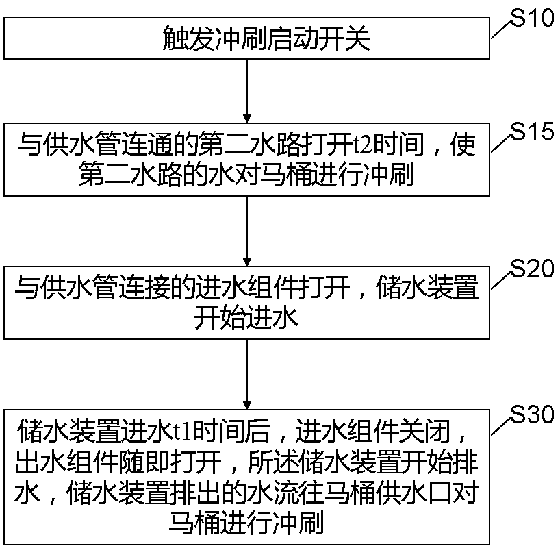
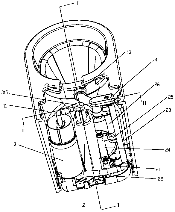
[0044] Such as figure 1 As shown, in the application state, the flushing mechanism is installed in the accommodating space 11 at the rear of the toilet 1, and the flushing mechanism includes a first water inlet pipe 21, a first water inlet control switch 22, and a first water outlet pipe 23; The first water inlet control switch 22 is connected to the water supply source through the first water inlet pipe 21. The water inlet assembly 35 is provided with a water inlet 351, and the water outlet assembly 36 is provided with a water outlet 361. The first water inlet control switch 22 is connected to the storage tank. The water inlet 351 of the water device 3 is connected, and the water outlet 361 of the water storage device 3 is connected with the water supply port 13 of the toilet through the first water outlet pipe 23 for flushing the toilet. The flush mechanism also has a second waterway, which includes a second water inlet pipe 24, a second water inlet control switch 25 and a s...

Embodiment 2

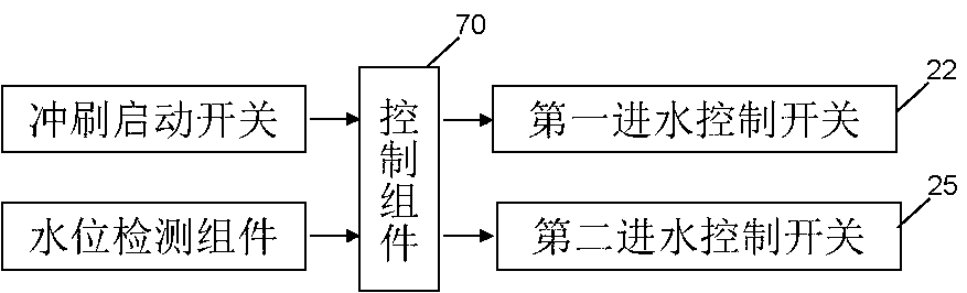
[0062] The difference between this embodiment and the first embodiment is that: the water outlet assembly 36 also uses a water outlet control switch 60 communicatively connected with the control assembly 70 to control water outlet, and the water outlet control switch 60 is preferably a solenoid valve. Therefore, the linkage control between the water inlet component and the water outlet component is realized through electronic control, that is, the control logic of the control component 70 is: when the first water inlet control switch 22 is turned on, the water outlet control switch 60 is turned off; the first water inlet control switch 22 When closed, the water outlet control switch 60 is opened.


PUM


Abstract

The invention discloses a closestool flushing mechanism and a flushing control method thereof. The closestool flushing mechanism comprises a water storage device provided with a water storage cavity,a water feeding component and a water draining component, wherein the water storage cavity is connected with a water pipe via the water feeding component; the water storage cavity is connected with the water inlet of the closestool via the water draining component. The closestool flushing mechanism is characterized in that the water feeding component and the water draining component are controlledin a linked manner, so that when the water feeding component is opened, the water draining component is closed, and water is stored in the water storage device; when the water feeding component is closed, the water draining component is opened, the water storage device drains water to flush the closestool. According to the closestool flushing mechanism provided by the invention, the water storagedevice is used for storing the water temporarily, when a water pressure is low, the waster also can be stored for flushing, and the flushing effect is ensured.

Description

technical field [0001] The invention relates to the technical field of toilets, in particular to a toilet flushing mechanism and a flushing control method thereof. Background technique [0002] Present toilet is generally provided with two outlet pipes, i.e. jet pipe and brush ring pipe. Part of the water flow flows through the brush ring pipe to scrub the inner ring surface of the toilet body, and the other part of the water flows out through the spray pipe to spray and rinse the bottom of the toilet body. Because the water of two water outlet pipes all comes to drain valve, and the water level of brush ring pipe is higher, the water yield of brush ring pipe is difficult to effectively guarantee. [0003] Simultaneously, existing toilet generally all has water storage device (as ceramic water tank), and before toilet is flushed, earlier by the water storage device store a certain amount of water for standby, just controls water to be discharged from water storage device wh...

Claims


Application Information

Patent Timeline
Patent Type & Authority Applications(China)
IPC IPC(8): E03D1/38E03D1/34
CPCE03D1/38E03D1/34
Inventor 江长发
Owner XIAMEN AXENT
Why Eureka
Try Eureka