
Auxiliary device for construction barricade and method of constructing barricade of auxiliary device

An auxiliary device and retaining wall technology, which is applied to safety devices, earth-moving drilling, mining equipment, etc., can solve the problems of increasing the construction cost of retaining walls, being easily damaged, and polluting the underground environment, so as to improve the reuse rate and avoid shaking. Collapse, the effect of increasing the disassembly rate

Pending Publication Date: 2019-11-05
临沂会宝岭铁矿有限公司 +1
View PDF1 Cites 0 Cited by
  • Summary
  • Abstract
  • Description
  • Claims
  • Application Information

AI Technical Summary

Problems solved by technology

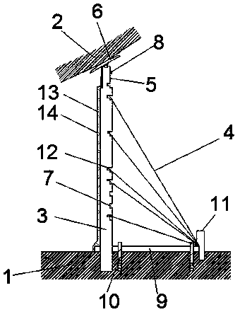
The retaining wall still has the following disadvantages during construction: 1) The column is not suitable for the construction of the retaining wall when the height of the top rock is inconsistent, so that the scope of application of the retaining wall is narrow; 2) When the retaining wall is constructed, the column is used Concrete is poured underground. After the construction is completed, the column is not easy to disassemble, and it is easily damaged after disassembly from the concrete, which reduces its compressive capacity and is not suitable for repeated use, which increases the cost of retaining wall construction and reduces the reuse of materials. 3) One end of the support bar of the retaining wall is directly in contact with the bottom plate. When the lateral pressure of the retaining wall is too large during pouring and filling, it is difficult for the end of the support bar in contact with the floor to withstand a large lateral force. The pressure is prone to deformation and slippage, and the unstable contact between the column and the top rock can easily lead to the collapse of the retaining wall and the pollution of the underground environment, which poses a great safety hazard
[0004] Therefore, there is an urgent need to provide an auxiliary device to solve the problems of low construction efficiency and collapse of the retaining wall and the difficulty of supporting the auxiliary support device to withstand the large lateral pressure during the pouring process

Method used


Image

  • Auxiliary device for construction barricade and method of constructing barricade of auxiliary device
  • Auxiliary device for construction barricade and method of constructing barricade of auxiliary device
  • Auxiliary device for construction barricade and method of constructing barricade of auxiliary device

Examples


Embodiment 1

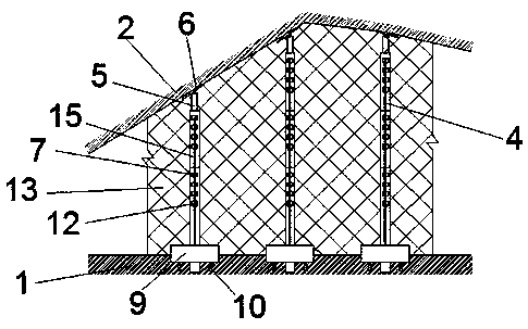
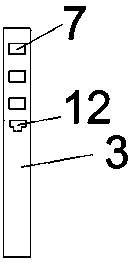
[0039] see Figure 1-3 , an auxiliary device for constructing a retaining wall, comprising a base plate 1 and a roof rock 2, a column 3 is arranged between the base plate 1 and the roof rock 2, and the bottom end of the column 3 extends into the base plate 1 excavated in advance In the fixing hole, and between it and the bottom plate 1, there are several supports arranged obliquely. The supports are steel bars 4. Connecting rod 15, the connecting rod 15 at the head end is detachably connected with the column 3, the connecting rod 15 at the head end refers to the connecting rod 15 at the bottom, and the connecting rod 15 at the tail end is detachably connected with the supporting cap , the connecting rod 15 at the tail end refers to the connecting rod 15 located at the top, the side of the column 3 away from the support is connected with a double-layer steel wire mesh 13, and a geotextile 14 is laid outside the steel wire mesh.

[0040] see Figure 4The detachable connection ...

Embodiment 2

[0050] The difference between this embodiment and Embodiment 1 is that the connection between the connecting rods 15, between the connecting rods 15 and the column 3, and the detachable connection between the connecting rods 15 and the supporting cap is different, and other structures are the same as those of Embodiment 1 same.

[0051] The top inwall of column 3 is provided with internal thread, and the outer wall of the second connecting rod 17 is provided with the external thread that matches with internal thread, and the inwall of the first connecting rod 16 is provided with internal thread, and the support bar 5 outer wall of supporting top solid cap is provided with. There are external threads, and the threaded connection is realized through the cooperation of the internal threads and the external threads, and the adjacent connecting rod 15, the connecting rod 15 and the column 3, and the connecting rod 15 are connected with the supporting cap to realize a detachable conn...

Embodiment 3

[0053] The difference between this embodiment and Embodiment 1 is that flange connections are used between the connecting rods 15, between the connecting rods 15 and the column 3, and between the connecting rods 15 and the supported top caps. Other structures are the same as those in the embodiment. 1 is the same.

[0054] Changes in the above technical features can be understood and implemented by those skilled in the art through written descriptions, so no additional drawings are provided for illustration.


PUM


Abstract

The invention discloses an auxiliary device for construction a barricade and a method of constructing the barricade of the auxiliary device. The auxiliary device comprises a bottom plate and top platemine rocks. Stand columns are arranged between the bottom plate and the top plate mine rocks. The bottom ends of the stand columns extend into fixing holes excavated in the bottom plate in advance. Aplurality of supporting parts arranged obliquely are arranged between the bottom ends of the stand columns and the bottom plate. The auxiliary device further comprises carrier top fixing nuts and a plurality of following rods which are connected in a head-to-tail manner and are connected detachably. The following rods located at the head end and the tail end are detachably connected with the stand columns and the carrier top fixing nuts. The auxiliary device is simple in structure and wide in application range, the requirements for constructing the barricade with the top plate mine rocks of different heights can be met, the method of adopting the auxiliary device for constructing the barricade is simple and high in operability, in the filling process, when the stand columns are filled, the lateral bearing ability is high, and safety and the construction efficiency of barricade constructing are improved.

Description

technical field [0001] The invention relates to the technical field of mining and mining, in particular to an auxiliary device for constructing a retaining wall and a method for constructing a retaining wall with the auxiliary device. Background technique [0002] With the gradual depletion of shallow buried and easy-to-mining mineral resources, the contradiction between the ever-growing demand for mineral resources and the difficulty of resource mining and the pressure of safety and environmental protection has become more and more prominent. The filling mining method has played an important role in solving this contradiction. It is widely used in the field of mining because of its characteristics of safe operation, delaying surface subsidence, and effectively preventing engineering geological disasters such as deep rockbursts. In the filling mining process, the construction of the filling retaining wall is an important work that must be completed before filling. The constr...

Claims


Application Information

Patent Timeline
Patent Type & Authority Applications(China)
IPC IPC(8): E21F15/04
CPCE21F15/04
Inventor 刘文华李向东张纪堂李强司书波张海云王正英胡贵发石帅盛佳王胜军徐新海翟利军
Owner 临沂会宝岭铁矿有限公司
Learn More