Vacuum measurement method and device based on optical frequency comb

A technology of vacuum measurement and optical frequency comb, which is applied to measurement devices, vacuum gauges, and fluid pressure measurement. The effect of sensitivity

Active Publication Date: 2019-11-05
INST OF MICROELECTRONICS CHINESE ACAD OF SCI
View PDF5 Cites 5 Cited by
  • Summary
  • Abstract
  • Description
  • Claims
  • Application Information

AI Technical Summary

Problems solved by technology

[0004] (1) The refractive index method can only measure the overall effect of the gas, but cannot obtain the gas composition and gas partial pressure information
Therefore, only the vacuum degree can be obtained, but the cleanliness information cannot be obtained
[0005] (2) Due to the limited frequency scanning range of current tunable diode lasers, when using TDLAS method to detect multiple gases, multiple lasers need to work at the same time, resulting in an increase in instrument cost
At the same time, the clean gas in the vacuum environment, such as nitrogen, has extremely weak absorption in the visible and infrared bands, which is not conducive to the measurement of absorption spectroscopy

Method used


Image

  • Vacuum measurement method and device based on optical frequency comb
  • Vacuum measurement method and device based on optical frequency comb
  • Vacuum measurement method and device based on optical frequency comb

Examples


Embodiment Construction

[0045] In order to make the object, technical solution and advantages of the present invention clearer, the present invention will be further described in detail below in conjunction with specific embodiments and with reference to the accompanying drawings.

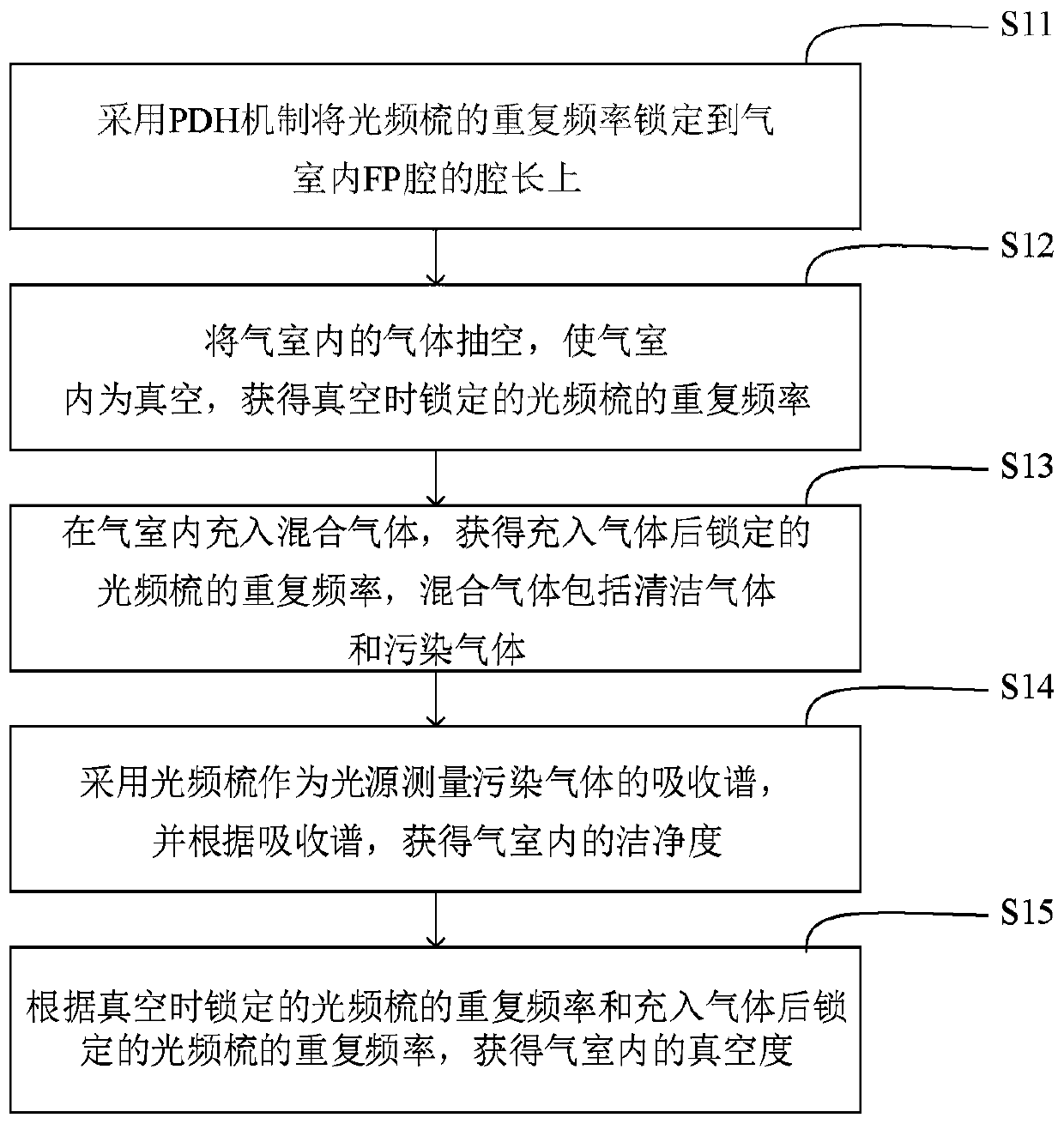
[0046] According to one aspect of the present invention, a vacuum measurement method based on an optical frequency comb is provided, such as figure 1 shown, including:

[0047] S11, using the PDH mechanism to lock the repetition frequency of the optical frequency comb to the cavity length of the FP cavity in the gas chamber;

[0048] S12, evacuating the gas in the gas chamber, making the gas chamber a vacuum, and obtaining the repetition frequency of the optical frequency comb locked in vacuum;

[0049] S13, filling the gas chamber with a mixed gas to obtain the repetition frequency of the locked optical frequency comb after filling the gas, and the mixed gas includes clean gas and polluted gas;

[0050] S14, using an o...


PUM


Abstract

The invention provides a vacuum measurement method and device based on an optimal frequency comb, and belongs to the technical field of vacuum measurement. The vacuum measurement method based on the optimal frequency comb comprises the steps of adopting a PDH mechanism for locking a repetition frequency of the optimal frequency comb to the cavity length of an FP cavity in a gas chamber; pumping out all gas in the gas chamber to make the interior of the gas chamber vacuumed, and then obtaining a locked repetition frequency of the optimal frequency comb during vacuum; filling the gas chamber with mixed gas, obtaining a locked repetition frequency of the optimal frequency comb after the gas chamber is filled with the gas, wherein the mixed gas comprises clean gas and pollution gas; adopting the optimal frequency comb as a light source to measure an absorption spectrum of the pollution gas, and obtaining the cleanliness of the interior of the gas chamber according to the absorption spectrum; obtaining vacuum degree in the gas chamber according to the locked repetition frequency of the optimal frequency comb during vacuum and the locked repetition frequency of the optimal frequency combafter the gas chamber is filled with the gas. According to the vacuum measurement method and device, by utilizing the characteristic of a wide spectrum of the optimal frequency comb, partial pressures of various gas components can be measured simultaneously, and the cleanliness is measured while the vacuum degree of the vacuum environment is measured.

Description

technical field [0001] The invention relates to the technical field of vacuum measurement, in particular to a vacuum measurement method and device based on an optical frequency comb. Background technique [0002] Extreme ultraviolet lithography machines, inertial confinement nuclear fusion national ignition devices, and long-life vacuum electronic devices all put forward requirements for the vacuum degree and cleanliness of the vacuum environment. At present, mass spectrometers and thin-film capacitance gauges are mostly used to monitor the vacuum environment. In recent years, the physical standards corresponding to many measurement parameters have begun to transform into quantum standards, and the vacuum measurement method based on optical means has become a research hotspot in the field of international vacuum measurement. The vacuum measurement methods based on optical means mainly include refractive index measurement and absorption spectrum measurement. The refractive ...

Claims


Application Information

Patent Timeline
Patent Type & Authority Applications(China)
IPC IPC(8): G01L21/00
CPCG01L21/00
Inventor 石俊凯周维虎黎尧陈晓梅刘立拓吴晓斌王魁波王宇
Owner INST OF MICROELECTRONICS CHINESE ACAD OF SCI
Why Eureka
Try Eureka