Separation and dust collection assembly and dust collector with same

A technology of separating sets and components, applied in vacuum cleaners, suction filters, household appliances, etc., can solve problems such as easy accumulation of dust and turbulent air flow at the dust-gas separator, so as to prevent dust, increase volume, reduce disordered effect

Pending Publication Date: 2019-11-08
SKYBEST ELECTRIC APPLIANCE SUZHOU CO LTD
View PDF0 Cites 2 Cited by
  • Summary
  • Abstract
  • Description
  • Claims
  • Application Information

AI Technical Summary

Problems solved by technology

[0005] In order to solve at least one of the problems in the prior art such as eddy currents in the idle space in the dust-gas separator, turbulent air flow at the dust-gas separator, and easy accumulation of dust to block th

Method used


Image

  • Separation and dust collection assembly and dust collector with same
  • Separation and dust collection assembly and dust collector with same
  • Separation and dust collection assembly and dust collector with same

Examples


Embodiment 1

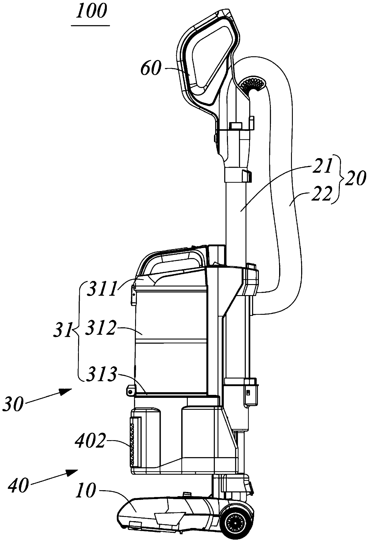
[0054] Such as Figure 1 to Figure 5 A preferred embodiment of the vacuum cleaner of the present invention is shown. The vacuum cleaner 100 is illustrated as an upright vacuum cleaner in this embodiment, but it is certainly not limited thereto. The vacuum cleaner of the present invention can also be implemented as a horizontal vacuum cleaner, a portable vacuum cleaner, a robot vacuum cleaner / sweeping floor machine and so on.

[0055] In this example, see figure 1 , The vacuum cleaner 100 includes a working head assembly 10 , a pipe assembly 20 , a separated dust collection assembly 30 , a suction assembly 40 and a handle assembly 60 .

[0056] The working head assembly 10 includes any one of ground brushes, round brushes, sweeping brushes, flat suction or other types of brushes or suction heads. The working head assembly 10 is formed with a suction port of the vacuum cleaner 100 .

[0057] The tube assembly 20 includes a rigid straight tube 21 extending longitudinally and a ...

Embodiment 2

[0094] ginseng Figure 6 to Figure 8 , shows another preferred embodiment of the present invention, and components with the same or similar features as in Embodiment 1 are marked with the same symbols as in Embodiment 1 combined with the letter "a" in this embodiment.

[0095] The difference between this embodiment and Embodiment 1 mainly lies in: the connection mode between the skirt and the main mechanism. The following will only describe this difference in detail, and other parts that are the same as those in Embodiment 1 will not be repeated here.

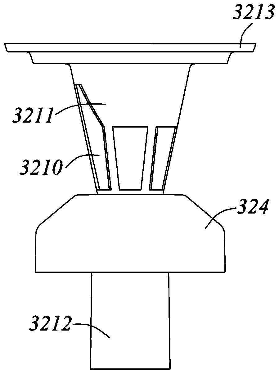
[0096] ginseng Figure 6 to Figure 8 Different from the integral arrangement of the skirt 324 and the separation cylinder 3211 in Embodiment 1, the skirt 324a and the separation cylinder 3211a are separately provided in this embodiment, and the skirt 324a is assembled and sleeved outside the main mechanism 321a.

[0097]Specifically, the top middle of the skirt 324a has a channel 3241a; the main body mechanism 321a is provide...

Embodiment 3

[0101] ginseng Figure 9 , shows another preferred embodiment of the present invention, and components with the same or similar features as those in Embodiment 1 are marked with the same symbols as in Embodiment 1 combined with the letter "b" in this embodiment.

[0102] The difference between this embodiment and Embodiment 1 mainly lies in the extension direction of the air inlet of the dust cup. The following will only describe this difference in detail, and other parts that are the same as those in Embodiment 1 will not be repeated here.

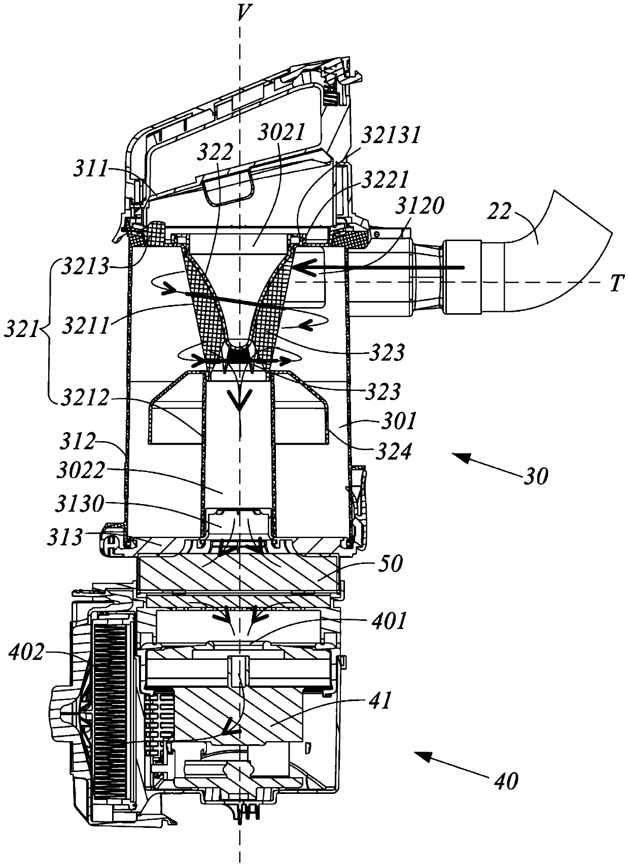
[0103] ginseng Figure 9 Unlike the extending direction T of the air inlet 3120 in Embodiment 1 which is the tangent to the side wall 312 of the dust cup 31, in this embodiment, the extending direction Tb of the air inlet 3120b is not the tangent to the side wall 312b of the dust cup 31b. Specifically, in this embodiment, the side wall 312b is in the shape of a cylinder arranged around the central axis Vb, and its air inlet 3120b extend...


PUM


Abstract

The invention provides a dust collector and a separation and dust collection assembly thereof. The separation and dust collection assembly comprises a dust cup and a dust and gas separator located inthe dust cup; the dust cup comprises a cylindrical side wall, a closed cover plate arranged at one axial end of the side wall, a base plate arranged at the other axial end of the side wall, and an airoutlet formed in the base plate; the dust and gas separator comprises a main body mechanism and an air guide cover; the main body mechanism comprises a separation cylinder with a plurality of separation openings, an assembling part connected with the first axial end of the separation cylinder and an air outlet cylinder connected with the second axial end of the separation cylinder; the air guidecover is hermetically connected to the assembling part and extends into the separation cylinder; an air guide cavity is formed between the air guide cover and the separation cylinder; the air guide cavity communicates with the air outlet through the air outlet cylinder; a closed cavity is formed between the air guide cover and the cover plate; and the closed cavity and the air guide cavity are sealed and isolated by the air guide cover, so that the air kinetic energy loss caused by vortex is reduced.

Description

technical field [0001] The invention belongs to the technical field of cleaning appliances, in particular to a separated dust collection assembly and a vacuum cleaner with the separation dust collection assembly. Background technique [0002] A vacuum cleaner is a cleaning appliance used to remove dust from floors, carpets, walls, furniture, clothing, and various gaps. It usually includes a working head assembly, a pipe assembly, a separation dust collection assembly, and a suction assembly. Wherein, when the vacuum cleaner is performing cleaning operations, driven by the suction assembly, the dust-laden airflow enters the vacuum cleaner from the outside from the working head assembly, and enters the separation dust collection assembly along the pipe assembly. In the process, a clean airflow is formed after being processed by the dust-gas separator of the separation dust collection assembly, and the separated dust is collected in the dust cup of the separation dust collectio...

Claims


Application Information

Patent Timeline
IPC IPC(8): A47L9/10A47L9/16A47L9/00
CPCA47L9/00A47L9/102A47L9/1683
Inventor 刘海平夏磊
Owner SKYBEST ELECTRIC APPLIANCE SUZHOU CO LTD
Why Eureka
Try Eureka