Device for classifying silicon carbide

A technology of silicon carbide and silicon carbide slurry, which is applied in the direction of solid separation, wet separation, chemical instruments and methods, etc., can solve the problems of long and complicated process, achieve the effect of continuous feeding and improve classification efficiency

Pending Publication Date: 2019-11-08
CHINA ENFI ENGINEERING CORPORATION
View PDF0 Cites 0 Cited by
  • Summary
  • Abstract
  • Description
  • Claims
  • Application Information

AI Technical Summary

Problems solved by technology

Since the ultrasonic vibrating screen can only be dry screened, drying and grinding proc

Method used


Image

  • Device for classifying silicon carbide
  • Device for classifying silicon carbide
  • Device for classifying silicon carbide

Examples


Embodiment 1

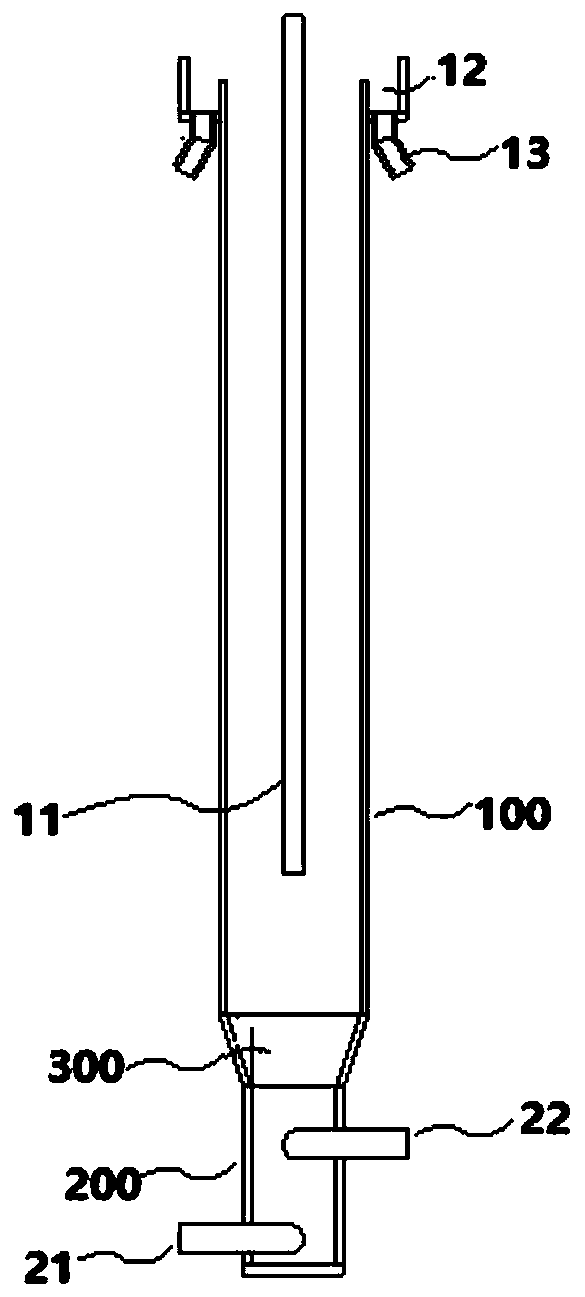
[0052] A device for grading silicon carbide comprises, from top to bottom: an upflow column, a bottom flow column and a transition column.

[0053] The top of the upflow column is open, and the upflow column is composed of multi-section sub-columns connected by flanges, including silicon carbide slurry inlet pipe, overflow tank, upflow outlet, middle outflow outlet and water supply pipe. Among them, the silicon carbide slurry inlet pipe extends from the top of the upflow column along the central axis of the upflow column to the inside of the upflow column; the overflow groove is arranged on the outer wall of the top of the upflow column, and in the height direction, the overflow The outer wall of the groove is higher than the outer wall of the upper column; the upper outlet is set at the bottom of the overflow tank; the middle outlet is located on the side wall of the upper column and is lower than the upper outlet in the height direction; the water supply pipe extends into the...

Embodiment 2

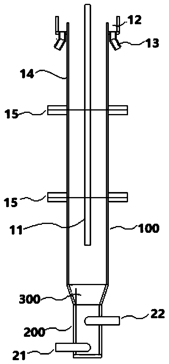
[0058] A device for grading silicon carbide comprises, from top to bottom: an upflow column, a bottom flow column and a transition column.

[0059] The top of the upflow column is open, and the upflow column is composed of multi-section sub-columns connected by flanges, including silicon carbide slurry inlet pipe, overflow tank, upflow outlet, middle outflow outlet and water supply pipe. Among them, the silicon carbide slurry inlet pipe extends from the top of the upflow column along the central axis of the upflow column to the inside of the upflow column; the overflow groove is arranged on the outer wall of the top of the upflow column, and in the height direction, the overflow The outer wall of the groove is higher than the outer wall of the upper column; the upper outlet is set at the bottom of the overflow tank; the middle outlet is located on the side wall of the upper column and is lower than the upper outlet in the height direction; the water supply pipe extends into the...

Embodiment 3

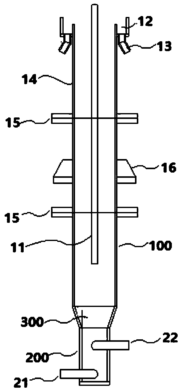
[0064] A device for grading silicon carbide comprises, from top to bottom: an upflow column, a bottom flow column and a transition column.

[0065] The top of the upflow column is open, and the upflow column is composed of multi-section sub-columns connected by flanges, including silicon carbide slurry inlet pipe, overflow tank, upflow outlet, middle outflow outlet and water supply pipe. Among them, the silicon carbide slurry inlet pipe extends from the top of the upflow column along the central axis of the upflow column to the inside of the upflow column; the overflow groove is arranged on the outer wall of the top of the upflow column, and in the height direction, the overflow The outer wall of the groove is higher than the outer wall of the upper column; the upper outlet is set at the bottom of the overflow tank; the middle outlet is located on the side wall of the upper column and is lower than the upper outlet in the height direction; the water supply pipe extends into the...


PUM

PropertyMeasurementUnit
Particle sizeaaaaaaaaaa

Abstract

The invention discloses a device for classifying silicon carbide. The device for classifying the silicon carbide comprises an upflow cylinder, an underflow cylinder and a transition cylinder, whereinthe top of the upflow cylinder is open and the upflow cylinder comprises a mixed slurry inlet pipe, an overflow groove and an upflow outlet; the mixed slurry inlet pipe extends into the upflow cylinder from the top of the upflow cylinder; the overflow groove is arranged on the outer side wall of the top of the upflow cylinder; and the overflow outlet is arranged at the bottom of the overflow groove. The underflow cylinder comprises a rotary water inlet pipe and an underflow outlet, wherein the rotary water inlet pipe is tangent to the side wall of the lower part of the underflow cylinder; thedischarge direction of the underflow outlet is tangent to the side wall of the upper part of the underflow cylinder; and the underflow outlet is positioned at the upper part of the rotary water inletpipe in the height direction. The transition cylinder is connected with the upflow cylinder and the underflow cylinder. By means of the device for classifying the silicon carbide, the classification of the silicon carbide particles with different specific gravities or different particle diameters can be achieved, and the classifying efficiency of the device for classifying the silicon carbide canbe remarkably improved.

Description

technical field [0001] The invention belongs to the field of silicon carbide processing, in particular, the invention relates to a device for classifying silicon carbide. Background technique [0002] Through quartz sand (SiO 2 ) and petroleum coke (carbon) reduction to prepare silicon carbide abrasives, the main process route is: raw material preparation-crushing-magnetic separation-water separation-ultrasonic sieving, etc. Among them, for the classification of silicon carbide in different particle size ranges, water separation and ultrasonic screening technologies are adopted in turn. Among them, the basic principle of the water separation method is to use the different sedimentation speeds of silicon carbide particles of different diameters in water to conduct particle size separation. The fine powder realizes the sieving function after receiving huge ultrasonic acceleration. Since the ultrasonic vibrating sieve can only be dry sieved, drying and grinding processes nee...

Claims


Application Information

Patent Timeline
IPC IPC(8): B03B5/30
CPCB03B5/30
Inventor 刘苏宁孙宁磊林洁媛刘国
Owner CHINA ENFI ENGINEERING CORPORATION
Why Eureka
Try Eureka