Mask assembly and manufacturing method of Mini LED backlight module

A manufacturing method and technology for a backlight module, applied in the direction of spraying devices, etc., can solve the problems of complex process, low spraying efficiency, and lack of mass production, and achieve the effect of simple process, high spraying efficiency, and mass production.

Active Publication Date: 2019-11-08
BOE TECH GRP CO LTD +1
View PDF18 Cites 6 Cited by
  • Summary
  • Abstract
  • Description
  • Claims
  • Application Information

AI Technical Summary

Problems solved by technology

[0007] The embodiment of the present invention provides a method for manufacturing a mask assembly and a Mini LED backlight module, which is used to solve the complicated process in the silicone coating method for forming a mouth-shaped wall around the light-emitting chip in the existing Mini LED backlight. , low spraying efficiency, lack of mass production and other insurmountable shortcomings

Method used


Image

  • Mask assembly and manufacturing method of Mini LED backlight module
  • Mask assembly and manufacturing method of Mini LED backlight module
  • Mask assembly and manufacturing method of Mini LED backlight module

Examples


Embodiment Construction

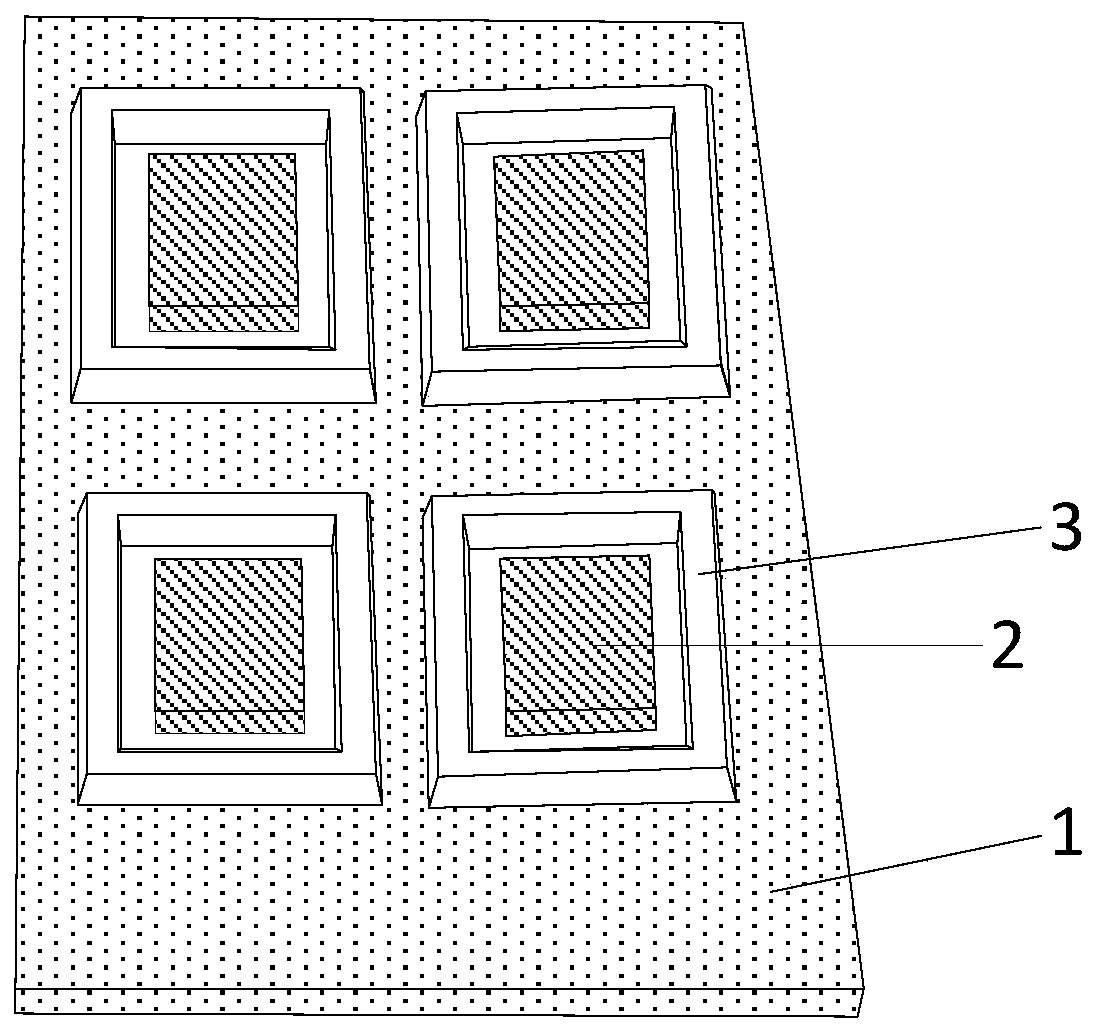
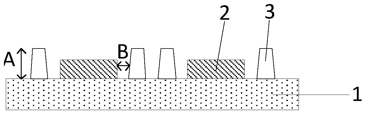
[0039] In order to make the objectives, technical solutions and advantages of the present invention clearer, specific implementations of the mask assembly and Mini LED backlight module manufacturing method provided by the embodiments of the present invention will be described in detail below with reference to the accompanying drawings. It should be understood that the preferred embodiments described below are only used to illustrate and explain the present invention, but not to limit the present invention. And if there is no conflict, the embodiments in the application and the features in the embodiments can be combined with each other. It should be noted that the thickness and shape of each layer of the film in the drawings do not reflect the true ratio, and the purpose is only to illustrate the content of the present invention. And the same or similar reference numerals indicate the same or similar elements or elements with the same or similar functions.

[0040] An embodiment...


PUM


Abstract

The invention discloses a mask assembly and a manufacturing method of a Mini LED backlight module. After luminous chips are subjected to crystal fixing, the mask assembly is pasted above the luminouschips, all mask regions correspond to the luminous chips one to one, thus, second shielding parts of the mask regions cover the luminous chips, spraying parts correspond to the positions of gaps in the peripheries of the luminous chips, then materials for manufacturing reflecting structures are sprayed to the positions of the gaps of the luminous chips through hollowed-out regions of the sprayingparts to form the reflecting structures, as the materials for manufacturing the reflecting structures can be simultaneously sprayed to the peripheries of the luminous chips, the procedures are simple,the consumed time is short, the spraying efficiency is high, and mass production is achieved; and in the spraying process, the second shielding parts shield the luminous chips, the spraying materialsare prevented from being sprayed onto the luminous chips, and therefore no large welding error is caused to the following Mini LED backlight module.

Description

Technical field [0001] The present invention relates to the field of display technology, in particular to a manufacturing method of a mask assembly and a Mini LED backlight module. Background technique [0002] Existing research has found that if white silica gel with a reflectivity of up to 95% made of mixed titanium dioxide is coated on the gap between the light-emitting chips on the MiniLED backlight substrate to form a mouth wall, such as Figure 1A with Figure 1B As shown, Figure 1A It is a schematic diagram of the top structure of Mini LED backlight, Figure 1B for Figure 1A As shown in the schematic cross-sectional structure of the Mini LED backlight, the formation of a mouth-shaped wall 3 in the gap between the light-emitting chips 2 on the base substrate 1 can greatly improve the light efficiency of the light-emitting chip 2 and thus the overall brightness of the Mini LED backlight. Parameters such as the height h of the shaped wall 3 and the distance d from the light emi...

Claims


Application Information

Patent Timeline
Patent Type & Authority Applications(China)
IPC IPC(8): B05B12/28
CPCB05B12/28
Inventor 杨山伟马俊杰翟明卢元达岂林霞
Owner BOE TECH GRP CO LTD
Why Eureka
Try Eureka