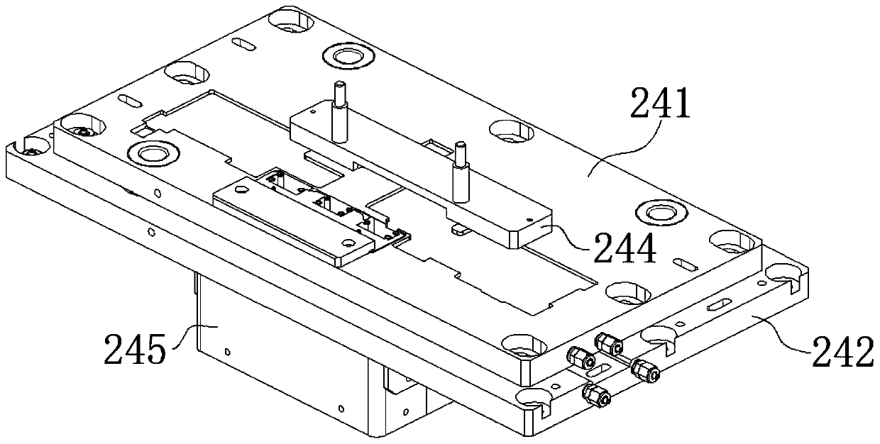
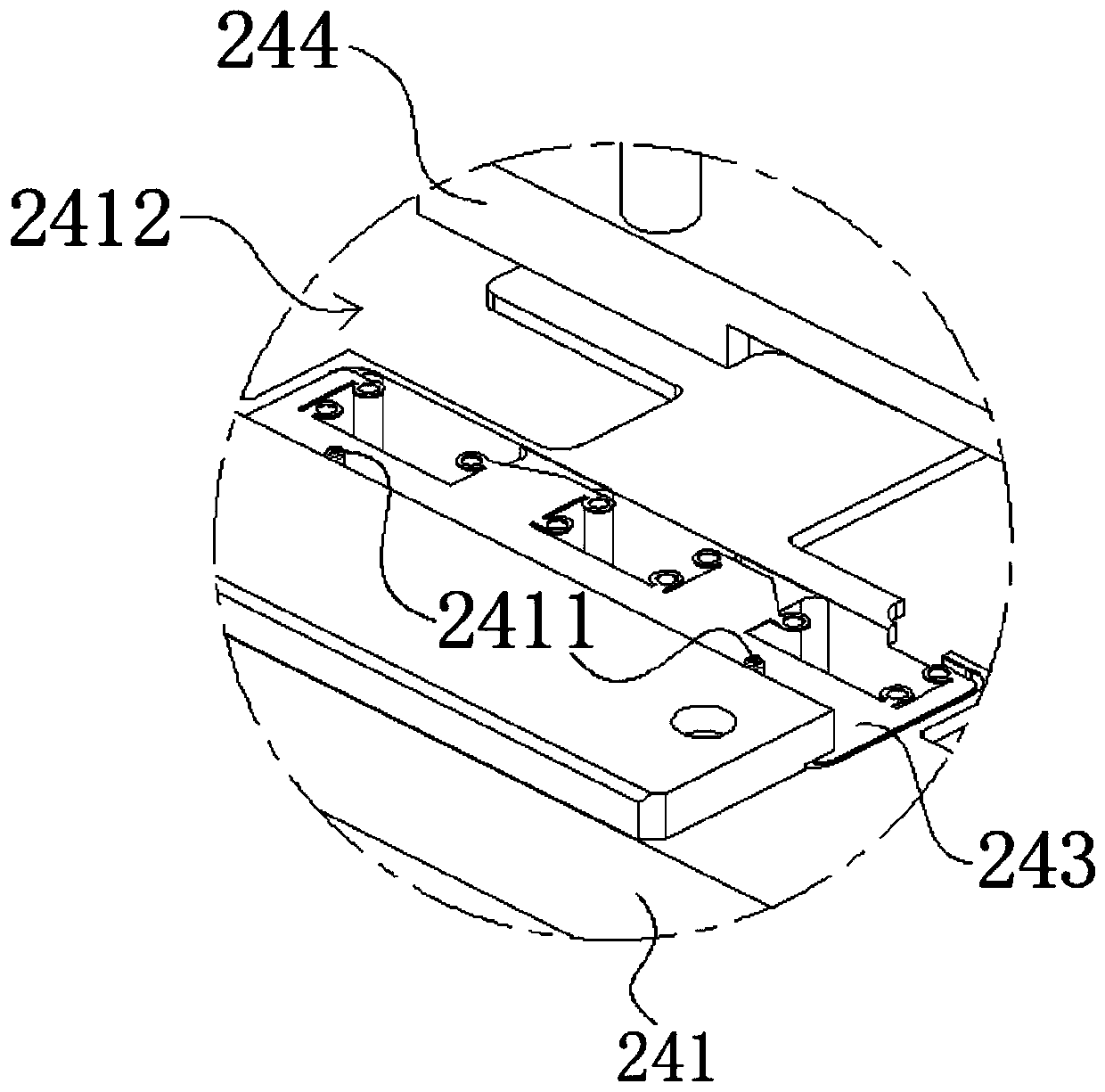
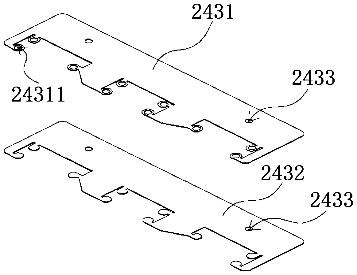
Jig assembly used for hot melting and hot-melting mechanism

A hot-melt and jig technology, applied in electrical components, printed circuit manufacturing, printed circuits, etc., can solve the problems of complex structure of hot-melt mechanism, increase energy loss, easy to produce errors, etc., to improve heat utilization efficiency and save energy. , the effect of easy maintenance

Pending Publication Date: 2019-11-08
SUZHOU RS TECH
View PDF0 Cites 1 Cited by
  • Summary
  • Abstract
  • Description
  • Claims
  • Application Information

AI Technical Summary

Problems solved by technology

[0003] In industry, hot-melt machines are widely used, mainly for welding plastic parts such as household appliances, car lights, and automotive fuses. A heater with a lower power is used to preheat the workpiece first; the hot-melt mechanism in the prior art includes a hot-melt head and a heater, and the heater is connected to the fixture body so that the heater preheats the product. When the fixture is in contact with the workpiece, the heater works to heat the workpiece, thereby reducing the temperature difference between the hot-melt head and the workpiece. For example, the above-mentioned hot-melt mechanism heats the workpiece by adding a heater. When multiple processing points on the workpiece need to be When hot-melting, in order to meet the requirement of preheating the workpiece at each hot-melt head, it is necessary to increase the number of heaters equal to the number of hot-melt heads, which makes the structure of the hot-melt mechanism complex and increases energy consumption; The machine controls the heating of the heating plate through the hot-melt component and the electric control box, preheats the workpiece first, and then controls the heating plate to heat-melt the workpiece, although the same hot-melt component is used to heat the workpiece separately Preheating and hot melting, but in this invention, the electric control box needs to control the preheating and hot melting time, which makes the mechanism more troublesome in use, and it is necessary to control the preheating and hot melting time, which is prone to errors

Method used


Image

  • Jig assembly used for hot melting and hot-melting mechanism
  • Jig assembly used for hot melting and hot-melting mechanism
  • Jig assembly used for hot melting and hot-melting mechanism

Examples


Embodiment Construction

[0038]The present invention will be further described in detail below in conjunction with the accompanying drawings, and the aforementioned and other objects, features, aspects and advantages of the present invention will become more apparent, so that those skilled in the art can implement them with reference to the description. In the drawings, the shapes and dimensions may be exaggerated for clarity, and the same reference numerals will be used throughout to designate the same or like parts. In the following description, terms such as center, thickness, height, length, front, back, rear, left, right, top, bottom, upper, lower, etc. are based on the orientation or positional relationship shown in the drawings. In particular, "height" corresponds to the dimension from top to bottom, "width" corresponds to the dimension from left to right, and "depth" corresponds to the dimension from front to back. These relative terms are for convenience of description and are generally not i...


PUM


Abstract

The invention provides a jig assembly used for hot melting. The jig assembly used for hot melting comprises a jig body. The jig body comprises a bearing plate and a forming sheet, wherein the formingsheet is mounted on the bearing plate and comprises a heat-conduction layer and a shaping layer, and the forming sheet is mounted on the bearing plate; forming holes which are consistent with a forming shape are formed in the shaping layer; the heat-conduction layer is attached to one sides of the forming holes, and an external heat source is arranged on the side close to the heat-conduction layer; a pressure device is arranged on the side close to the shaping layer; and the forming sheet is heated through the external heat source, and a workpiece is fixed to the bearing plate through the pressing device, so that a to-be-hot melted part of the workpiece is melted and then solidified to be in the shape of the shaping holes. A hot-melting mechanism comprises a hot-melting device body, wherein the hot-melting device body comprises a jig body, a die set, a pressing assembly serving as the pressure device, and a hot-melting assembly serving as the external heat source, and in the hot-melting process, the pressing assembly, the hot-melting assembly and the jig body are combined. The hot-melting mechanism is simple and convenient to maintain.

Description

technical field [0001] The invention belongs to the field of hot-melt machines, and in particular relates to a jig assembly for hot-melt, and also specifically relates to a hot-melt mechanism. Background technique [0002] The hot melt machine transfers the heat of the heater to the welding surface of the circuit board by means of electric heating to melt the surface, and then quickly withdraws the heater to melt and solidify the welding surface of the circuit board into the required connection port. instrument. [0003] In industry, hot-melt machines are widely used, mainly for welding plastic parts such as household appliances, car lights, and automotive fuses. A heater with a lower power is used to preheat the workpiece first; the hot-melt mechanism in the prior art includes a hot-melt head and a heater, and the heater is connected to the fixture body so that the heater preheats the product. When the fixture is in contact with the workpiece, the heater works to heat the...

Claims


Application Information

Patent Timeline
Patent Type & Authority Applications(China)
IPC IPC(8): B29C65/18B29C65/10H05K3/00
CPCB29C65/10B29C65/18B29C66/814B29C66/81812B29C66/9241H05K3/0011H05K3/0014
Inventor 吴加富缪磊马纪飞赵洪文太平马伟
Owner SUZHOU RS TECH
Why Eureka
Try Eureka