Energy-saving control method for electric automobile driven by four-wheel hub motor

A hub motor and electric vehicle technology, applied in the field of control, can solve the problems of small scope of application, not making full use of the advantages and potential of four-wheel hub motors to drive electric vehicles, and not combining energy-saving control and stability control with vehicle active safety control.

Active Publication Date: 2019-11-08
JILIN UNIV
View PDF7 Cites 10 Cited by
  • Summary
  • Abstract
  • Description
  • Claims
  • Application Information

AI Technical Summary

Problems solved by technology

[0004] 1) Most of the existing energy-saving control methods for electric vehicles driven by four-wheel hub motors are based on traffic information, which optimizes the driving force, speed, and path of the vehicle at the traffic level, and does not make full use of the advantages and potential of electric vehicles driven by four-wheel hub motors. ; 2) Most of the existing energy-saving control methods only consider reducing energy consumption, and do not combine energy-saving control with stability control and vehicle active safety control, which increases the safety risk of vehicles while reducing energy consumption;
[0005] 3) Most of the existing energy-saving control methods are based on simple vehicle models and linear tire force models, which do not consider the nonlinear characteristics of tire forces or do not accurately express their nonlinear characteristics, and cannot be used under extreme conditions such as high speed and low adhesion , the scope of application is small

Method used


Image

  • Energy-saving control method for electric automobile driven by four-wheel hub motor
  • Energy-saving control method for electric automobile driven by four-wheel hub motor
  • Energy-saving control method for electric automobile driven by four-wheel hub motor

Examples


Embodiment Construction

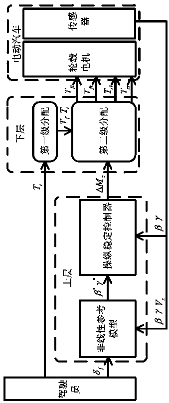
[0110] The invention overcomes the shortcomings of the existing methods, and provides an energy-saving control method for the electric vehicle based on a layered control structure for an electric vehicle whose four wheels are hub motors. The hierarchical control method is divided into upper and lower layers,

[0111] The upper layer calculates the ideal vehicle state according to the driver's needs, and outputs the additional yaw moment to make the actual state of the vehicle track the ideal state, more precisely, to make the actual yaw rate of the vehicle track the ideal value, thereby achieving energy saving and stability the goal of. According to the additional yaw torque output by the upper layer, the lower layer optimally allocates the driver’s total torque demand to the four in-wheel motors through a two-stage distribution. Based on these objectives and constraints, the total torque output by the driver is optimally distributed to the front and rear axles of the vehicle...


PUM


Abstract

The invention discloses an energy-saving control method for an electric automobile driven by a four-wheel hub motor, and belongs to the technical field of control. The energy-saving control method forthe electric automobile driven by the four-wheel hub motor aims to achieve energy saving of the electric automobile driven by the four-wheel hub motor through the reasonable design of the ideal stateof the automobile and the optimized distribution of the torque of the automobile and ensuring the operation stability of the automobile. The method comprises the steps that of S1, establishing a tirelongitudinal sliding model, S2, obtaining an expected vehicle yaw rate and a mass center yaw angle based on the vehicle model established in the step S1, S3, obtaining additional yaw moment requiredby vehicle stability, S4, introducing two virtual state quantities of the front wheel longitudinal slip rate and the rear wheel longitudinal slip rate based on a model predictive control theory, and S5, distributing the vehicle virtual rear wheel torque obtained in the step S4 to a left rear wheel and a right rear wheel of the vehicle. The method is not only applicable to conventional working conditions, but also applicable to limit working conditions such as high speed and low adhesion, the energy consumption is reduced, and the energy saving performance of the vehicle is improved.

Description

technical field [0001] The invention belongs to the technical field of control. Background technique [0002] New energy vehicles use clean energy, which reduces the emission of carbon dioxide and other gases, especially pure electric vehicles, which reduce the internal mechanical transmission system of the vehicle, simplify the structure, and have no exhaust emissions, resulting in less environmental pollution. Electric vehicles with four wheels with hub motors have greater potential in terms of vehicle energy saving and stability because the wheel torque can be independently controlled through vehicle dynamics control. [0003] The energy-saving control of electric vehicles driven by four-wheel hub motors has a good application prospect. Many researchers have carried out related research, but the following problems still exist at this stage: [0004] 1) Most of the existing energy-saving control methods for electric vehicles driven by four-wheel hub motors are based on tr...

Claims


Application Information

Patent Timeline
Patent Type & Authority Applications(China)
IPC IPC(8): B60L15/20B60W50/00
CPCB60L15/20B60L15/2045B60L2220/42B60L2220/44B60L2240/12B60L2240/24B60L2240/423B60W50/00B60W2050/0034B60W2050/0037Y02T10/72
Inventor 胡啸陈虹王萍
Owner JILIN UNIV
Why Eureka
Try Eureka