
Integrated concentration and dehydration machine for sludge

A technology of sludge concentration and integrated machine, which is applied in water/sludge/sewage treatment, sludge treatment, dehydration/drying/concentrated sludge treatment, etc. Affect problems such as electroosmosis, reduce the possibility of being thrown out of the cleaning cylinder, improve the efficiency of mud discharge, and clean the effect

Pending Publication Date: 2019-11-08
浙江科力尔环保设备股份有限公司
View PDF3 Cites 0 Cited by
  • Summary
  • Abstract
  • Description
  • Claims
  • Application Information

AI Technical Summary

Problems solved by technology

[0005] 1) During the angle adjustment process, once the angle between the second panel and the horizontal plane is too large (the sludge outlet is small), the sludge will easily accumulate near the inner side of the second panel, which will affect the fluidity of the sludge and lead to mud efficiency is low;
[0006] 2) Although the thickness of the sludge discharged from the second panel is consistent, the density is relatively low. The main reason is that: after the adjustment of the size of the sludge outlet is satisfied, due to the inclination angle of the second panel itself, the second panel has a relatively low impact on the sludge. Insufficient compaction force of mud
[0008] Although the above-mentioned patent can greatly improve the dehydration efficiency (increase by about 30%), the applicant found that, during the dehydration process, the sludge is easily bonded to the moving screen and extrusion plate (also known as: electrode plate), Furthermore, the electric osmosis is affected to a certain extent. Therefore, the applicant found that if the moving screen and the extruded plate can be further cleaned, the dehydration efficiency can be further improved.

Method used

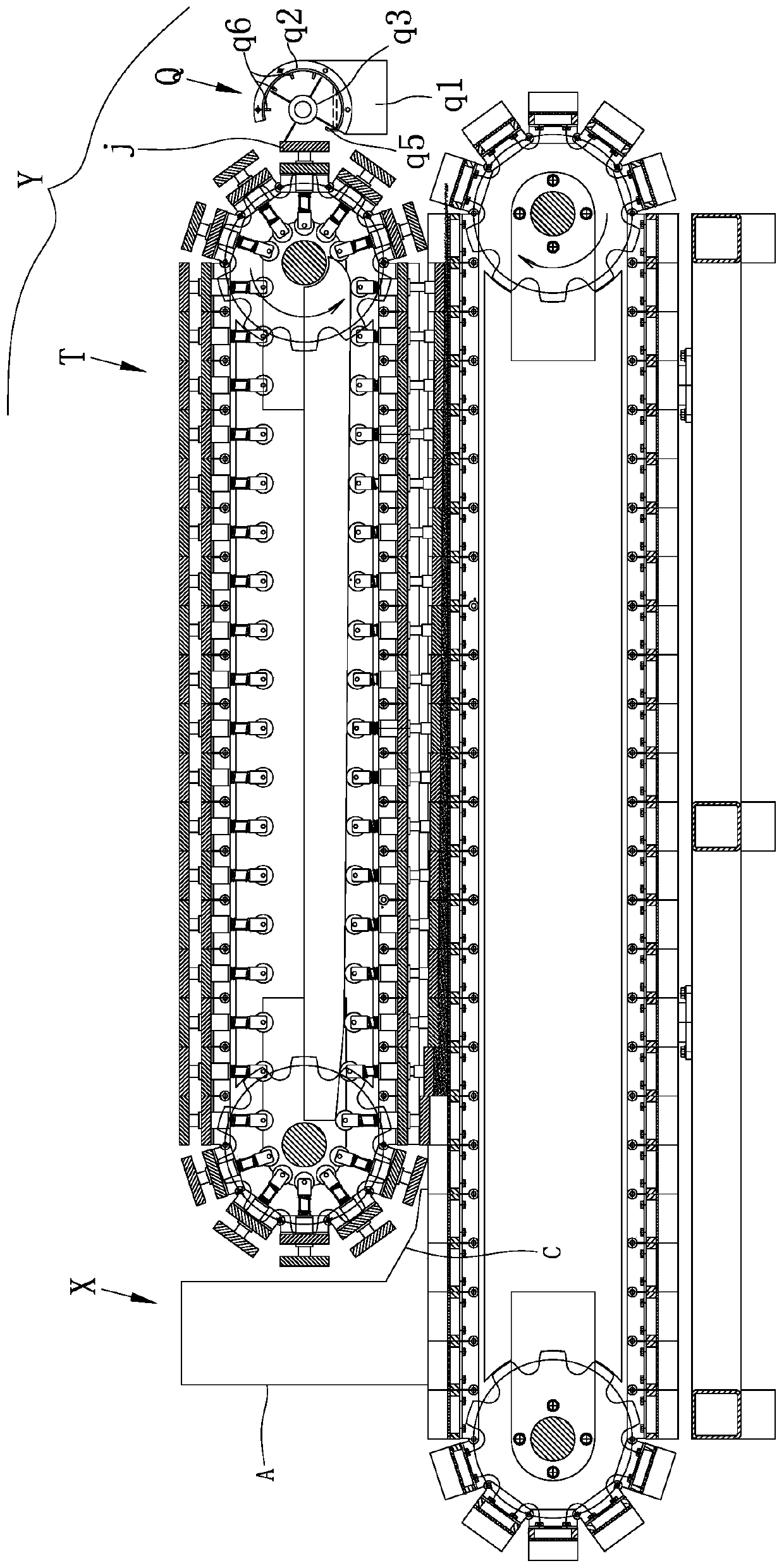
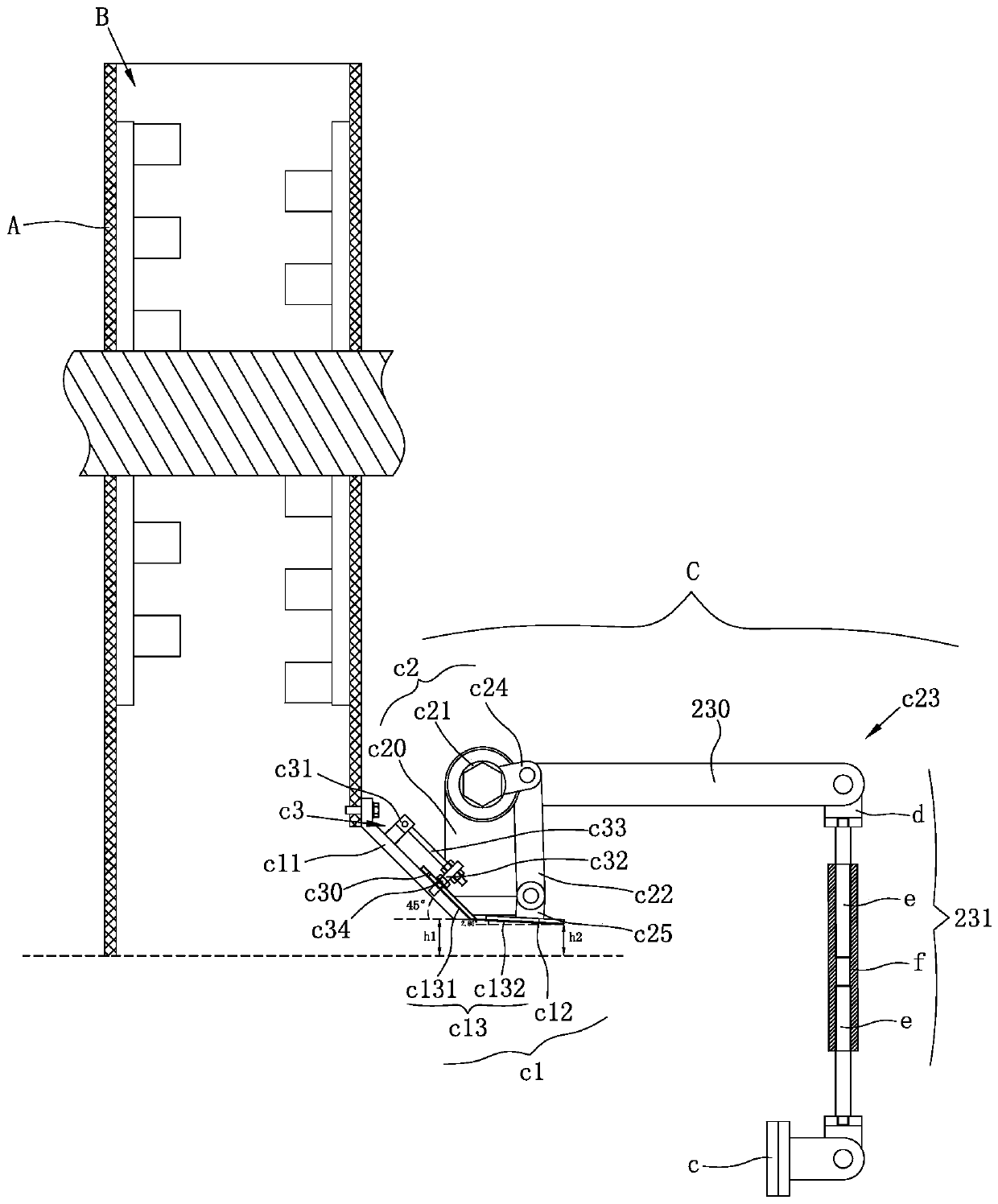
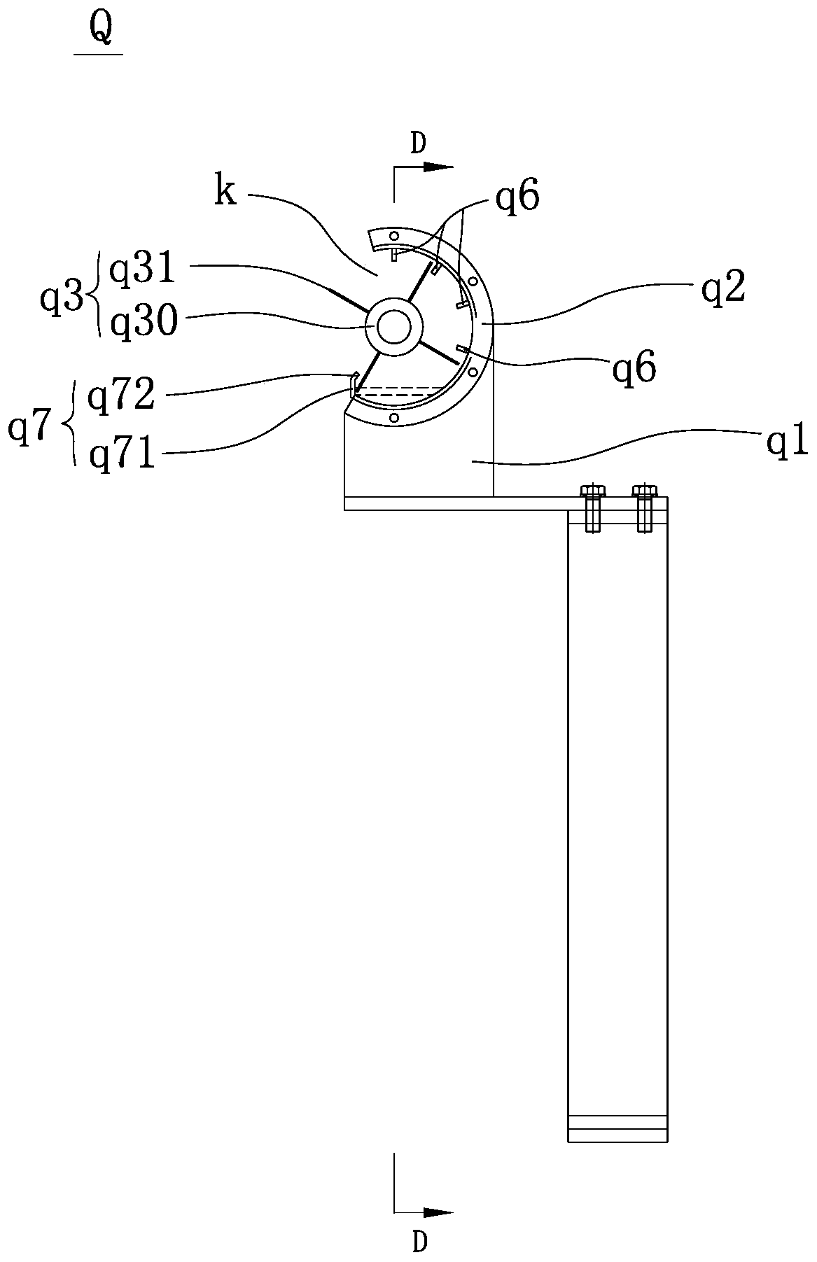

Image

  • Integrated concentration and dehydration machine for sludge
  • Integrated concentration and dehydration machine for sludge
  • Integrated concentration and dehydration machine for sludge

Examples


Embodiment Construction

[0046] In order to make the above objects, features and advantages of the present invention more obvious and understandable, the present invention will be described in detail below in conjunction with the accompanying drawings and specific embodiments. In the following description, numerous specific details are set forth in order to provide a thorough understanding of the present invention. However, the present invention can be implemented in many other ways different from those described here, and those skilled in the art can make similar improvements without departing from the connotation of the present invention, so the present invention is not limited by the specific embodiments disclosed below.

[0047] In describing the present invention, it should be understood that the terms "center", "longitudinal", "transverse", "length", "width", "thickness", "upper", "lower", "front", " Back", "Left", "Right", "Vertical", "Horizontal", "Top", "Bottom", "Inner", "Outer", "Clockwise"...


PUM

PropertyMeasurementUnit
thicknessaaaaaaaaaa

Abstract

The invention relates to an integrated concentration and dehydration machine for sludge. The integrated concentration and dehydration machine for sludge comprises a sludge concentrating device and anelectroosmotic dehydrator. The sludge concentrating device comprises a concentrating tank having a sludge inlet and a sludge outlet, a sludge scraping assembly, and a sludge discharging mechanism arranged at the sludge outlet of the concentrating tank. The electroosmotic dehydrator includes a dehydrator body having electrode plates, and a cleaning device for cleaning the electrode plates. According to the invention, the moisture content of sludge entering the electroosmotic dehydrator is reduced on the premise of improving the sludge discharging efficiency of the concentrating device; the efficiency and effect of electroosmosis are further improved through on-line cleaning of the surface of the electrode plates; and a sweeping member can realize self-cleaning during sweeping, thereby ensuring the cleaning quality of the sweeping member.

Description

technical field [0001] The invention belongs to the field of sludge treatment equipment, and in particular relates to a sludge concentration and dehydration integrated machine. Background technique [0002] With the development of social economy and the acceleration of urbanization, the amount of urban sewage treatment plants and the accompanying sludge has increased rapidly. According to relevant materials, in 2010, the sludge produced by my country's sewage treatment plants reached 300 million tons. Since the sludge must undergo biochemical and flocculation treatment during dehydration, and the dehydrated sludge contains a large amount of cell water and attached water, at present, almost all the existing equipment and technologies of sewage treatment plants can only reduce the water content of sludge to About 80%, if you want to meet the requirements of incineration - the water content of the sludge is lower than 50%, it will cost a lot of money, so almost all sewage treat...

Claims


Application Information

Patent Timeline
Patent Type & Authority Applications(China)
IPC IPC(8): C02F11/121C02F11/15
CPCC02F11/12C02F11/121
Inventor 王方清吴亮亮王浩程杨对国
Owner 浙江科力尔环保设备股份有限公司
Learn More