Sludge distribution filter pressing device

The technology of filter press plate and filter press is applied in the fields of filtration and separation, sludge treatment, water/sludge/sewage treatment, etc., which can solve the problems of low mud cake speed, large floor space and small processing capacity, etc. Achieve the effect of high mud removal efficiency and reduced floor space

Pending Publication Date: 2020-11-13
聂麒曌
View PDF0 Cites 1 Cited by
  • Summary
  • Abstract
  • Description
  • Claims
  • Application Information

AI Technical Summary

Problems solved by technology

[0003] Disadvantages of screw stacking sludge dewatering machine: 1. The maximum processing capacity of the designed model is about 400-800kg / h of sludge dry capacity, and enterprises with a scale of 300,000 tons or more in large sewage treatment plants may need more; 2. Screw stacking The machine cannot handle sludge containing hard particles such as sand and stones, otherwise the dynamic and static rings and screw shafts will be worn; 3. The treated sludge must be added with flocculants, and must be able to form good flocs before it can be processed, otherwise It is prone to the phenomenon of mud running in the dynamic and static ring; 4. The equipment realizes continuous operation, and the moisture content of the sludge is generally about 80%.
Disadvantages: high moisture content of sludge, high energy consumption, difficult maintenance
The disadvantage is that the processing capacity is small, and it is troublesome to replace the filter cloth
[0007] Due to different structural forms, the process principles of each filter press equipment are not the same, but from the perspective of dehydration effect and degree of automation, there is no equipment that can operate fully automatically and ensure that the dehydration rate is below 38%.
At the same time, the automation degree of the existing filter press system is relatively low, the labor cost is high, the floor area is large, the mud cake output speed is low, and the requirements for filter cloth are high.

Method used


Image

  • Sludge distribution filter pressing device
  • Sludge distribution filter pressing device
  • Sludge distribution filter pressing device

Examples


Embodiment Construction

[0060] The present invention will be described in detail below in conjunction with the accompanying drawings and specific embodiments.

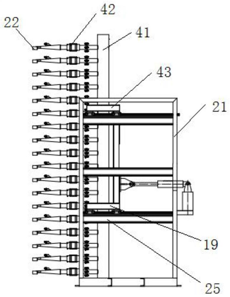
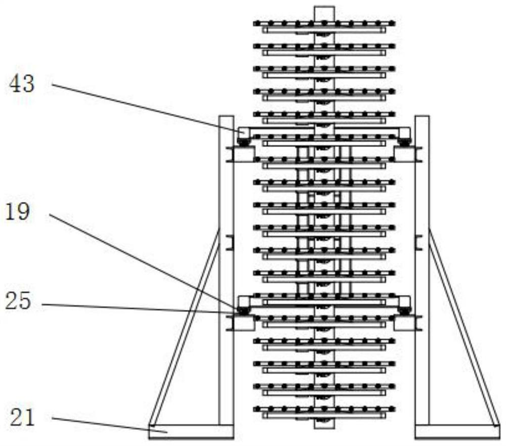
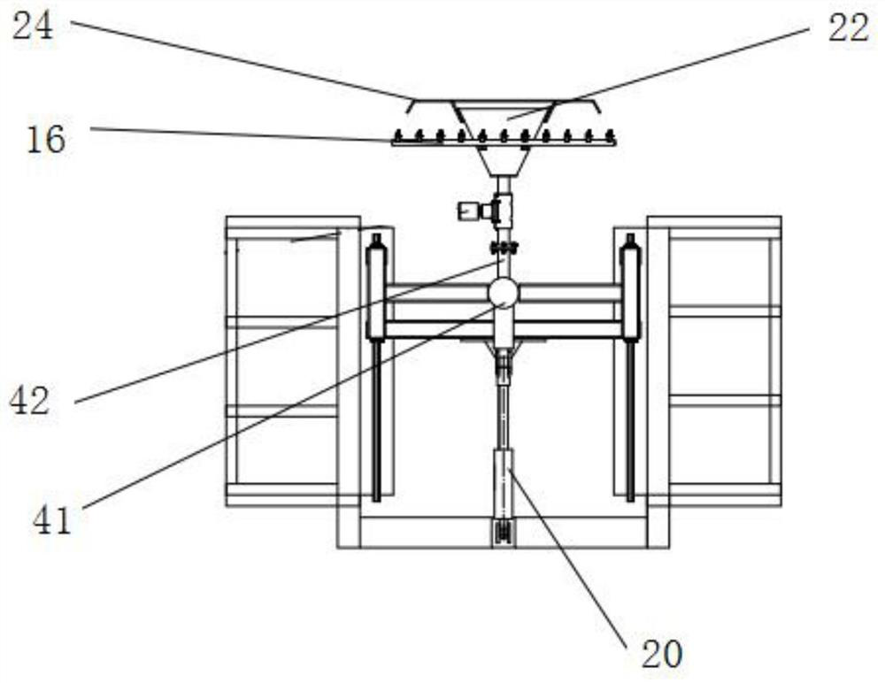
[0061] One, the present invention provides a kind of cloth mud press filter device, such as Figure 4-5As shown, it includes a mud distribution machine and a filter press set beside its mud distribution nozzle 22, including a filter press assembly, a lifting mechanism and a press 1. The filter press and the mud distribution machine are two pieces of equipment that work together. When each filter plate 15 of the filter press is opened, the mud distribution nozzle 22 advances horizontally between each filter plate 15 to start the mud distribution; When the machine is about to start the filter press action, the mud distribution nozzle 22 retreats horizontally to stop the mud distribution, and the filter press plates 15 are combined to filter the materials distributed between the filter press plates 15 . The materials to be treated can be sewage...


PUM


Abstract

The invention discloses a sludge distributing and filter pressing device which comprises a sludge distribution machine and a filter press which are matched to work, wherein the sludge distribution machine comprises a sludge distribution main pipe, a plurality of sludge distribution branch pipes and a movable supporting mechanism; the filter press is arranged beside a distribution outlet of the sludge distribution machine and comprises a filter pressing assembly, a lifting mechanism and a press machine. The effects of high solid-liquid separation sludge discharge speed, high dehydration rate, low requirement on filter cloth and small occupied area of the filter pressing sludge distribution device are achieved.

Description

technical field [0001] The invention belongs to the technical field of solid-liquid separation, and in particular relates to a mud distribution press filter device. Background technique [0002] The process of separating solids from liquids is solid-liquid separation. There are many methods, such as sedimentation, filtration, membrane filtration, pressure filtration, vacuum, centrifuge and so on. Common solid-liquid separation equipment in the prior art includes screw stackers, cloth belt filter presses, spiral solid-liquid separators, and plate-and-frame filter presses. [0003] Disadvantages of snail stacking sludge dewatering machine: 1. The maximum processing capacity of the designed model is about 400-800kg / h of absolute dry sludge, and enterprises with a scale of 300,000 tons or more in large sewage treatment plants may need more; 2. Stacking snails The machine cannot handle sludge containing hard particles such as sand and stones, otherwise the dynamic and static rin...

Claims


Application Information

Patent Timeline
Patent Type & Authority Applications(China)
IPC IPC(8): B01D25/12B01D25/30B01D25/32B01D25/34B01D25/38C02F11/122
CPCB01D25/12B01D25/30B01D25/32B01D25/34B01D25/343B01D25/386C02F11/122
Inventor 不公告发明人
Owner 聂麒曌
Why Eureka
Try Eureka