Full-automatic solid-liquid separation system suitable for sludge treatment

A sewage treatment system and solid-liquid separation technology, applied in sludge treatment, water/sludge/sewage treatment, dehydration/drying/concentrated sludge treatment, etc. High labor costs and other issues, to achieve the effect of reduced floor area and high mud output efficiency

Pending Publication Date: 2020-11-13
聂麒曌
View PDF0 Cites 5 Cited by
  • Summary
  • Abstract
  • Description
  • Claims
  • Application Information

AI Technical Summary

Problems solved by technology

The disadvantage of the plate and frame filter press is that the processing capacity is small, and it is troublesome to replace the filter cloth.
[0003] To sum up, due to different structural forms, the process principles of each filter press equipment are not the same, but from the perspective of dehydration effect and degree of automation, there is currently no equipment that can operate fully automatically and ensure a dehydration rate of 38%. the following
At the same time, the automation degree of the existing filter press system is relatively low, the labor cost is high, the floor area is large, the mud cake output speed is low, and the requirements for filter cloth are high.

Method used


Image

  • Full-automatic solid-liquid separation system suitable for sludge treatment
  • Full-automatic solid-liquid separation system suitable for sludge treatment
  • Full-automatic solid-liquid separation system suitable for sludge treatment

Examples


Embodiment Construction

[0070] The present invention will be described in detail below in conjunction with the accompanying drawings and specific embodiments.

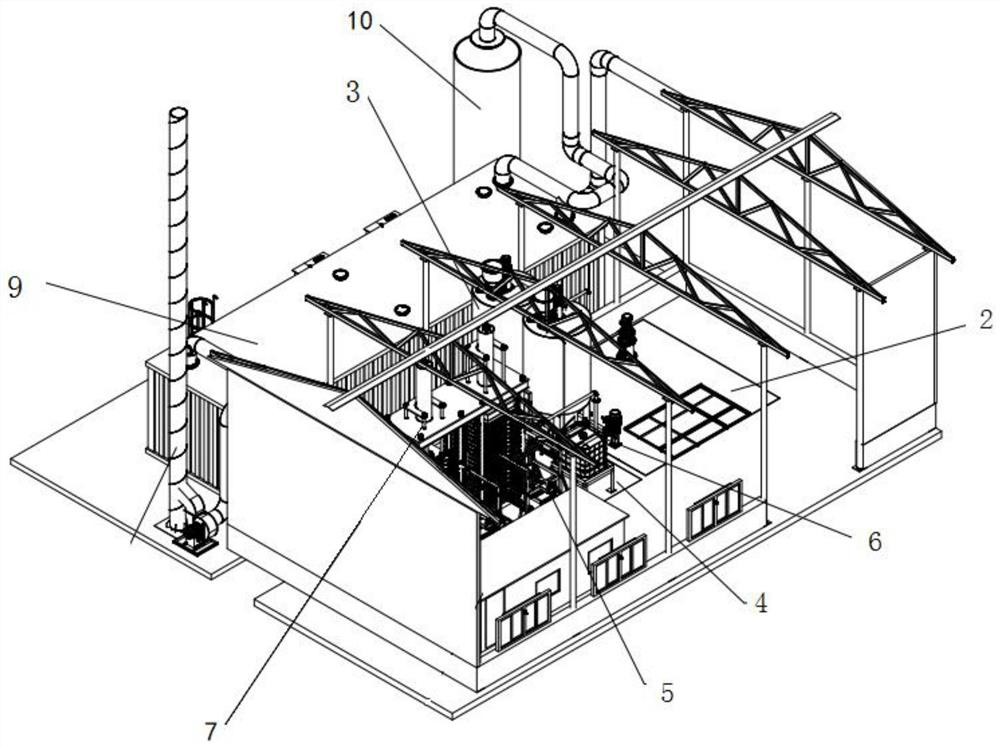
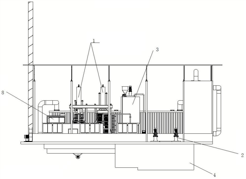
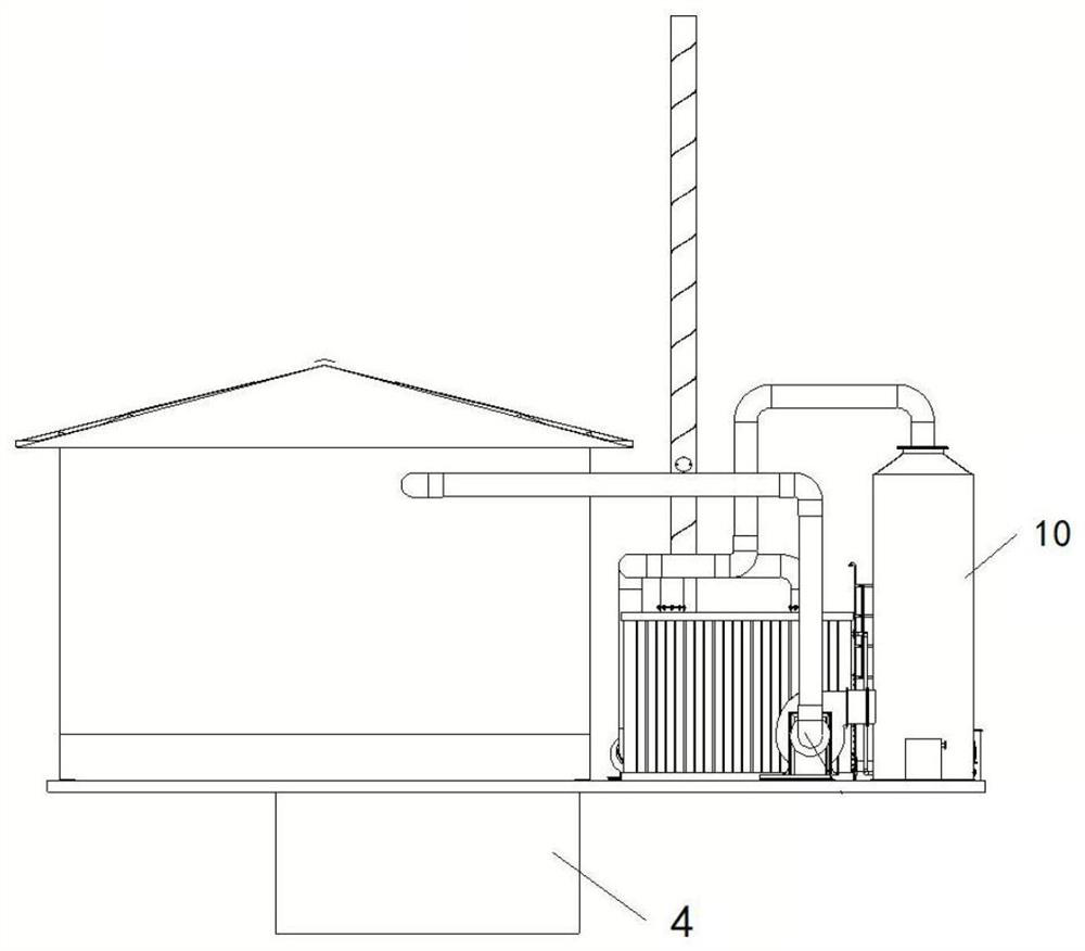
[0071] 1. The present invention provides a fully automatic solid-liquid separation system suitable for sludge treatment, such as Figure 1-3 As shown, it includes a material pretreatment system, a mud distributor 5 and a filter press 7; it may also include a mud cake collection system, a sewage treatment system and / or an air suction and biological deodorization device 9.

[0072] 1. The material pretreatment system includes a sludge mixing bin 2 and a conditioning tank 3, and may also include an automatic conditioning agent feeding device 6. Among them, the sludge mixing bin 2 is used to receive the materials to be processed. The source of the materials to be processed can be transported to the sludge mixing bin 2 by a solid-liquid transport vehicle, or directly at the site where various types of sludge need to be processed. The built-in pla...


PUM


Abstract

The invention discloses a full-automatic solid-liquid separation system suitable for sludge treatment. The full-automatic solid-liquid separation system comprises a material pretreatment system and asludge distribution filter pressing device. The material pre-treatment system comprises a sludge stirring bin which is used for accommodating and stirring cloth materials to be stirred; one or more conditioning tanks which are communicated with the sludge stirring bin and provided with an automatic conditioner feeding device; the sludge distribution filter pressing device comprises one or more sludge distributors, wherein inlets of the sludge distributors are communicated with the corresponding conditioning tanks; a filter press which is arranged beside the distribution outlet of the sludge distributor and comprises one or more filter pressing devices, wherein the number of the filter pressing devices is the same as that of the sludge distributors, the filter pressing devices are arrangedon the distribution side of the sludge distributor in a one-to-one correspondence mode, and each filter pressing device comprises a filter pressing assembly, a lifting mechanism and a press machine. The effects of high solid-liquid separation sludge discharge speed, high dehydration rate, low requirement on filter cloth and small occupied area of the filter pressing system are achieved.

Description

technical field [0001] The invention belongs to the technical field of solid-liquid separation, and in particular relates to a fully automatic solid-liquid separation system suitable for sludge treatment. Background technique [0002] The main function of the filter press is to separate sludge or water through mechanical kinetic energy. It has a wide range of uses. Common solid-liquid separation equipment in the prior art includes screw stackers, cloth belt filter presses, Spiral solid-liquid separator, plate and frame filter press. The disadvantage of the stacked screw sludge dewatering machine is that the equipment can work continuously, and the moisture content of the sludge is generally about 80%. The disadvantages of cloth belt filter press are high sludge moisture content, high energy consumption, and difficult maintenance. The moisture content of the solid after extrusion by the screw extrusion type solid-liquid separator is about 65-70%. The disadvantage of the pl...

Claims


Application Information

Patent Timeline
Patent Type & Authority Applications(China)
IPC IPC(8): C02F11/14C02F11/122B01D53/84B01D53/38B01D53/18
CPCB01D53/18B01D53/38B01D53/84C02F11/122C02F11/14Y02A50/20
Inventor 不公告发明人
Owner 聂麒曌
Why Eureka
Try Eureka