Assembly type building wall component
A building wall and prefabricated technology, which is applied in the direction of building components, building structures, buildings, etc., can solve problems such as the inability to guarantee the firmness and durability of the installation and connection of prefabricated building walls, troublesome installation and connection methods, etc., to achieve The connection is stable and firm, ensuring the effect of stability and firmness
- Summary
- Abstract
- Description
- Claims
- Application Information
AI Technical Summary
Problems solved by technology
Method used
Image
Examples
Embodiment 1
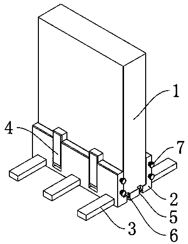
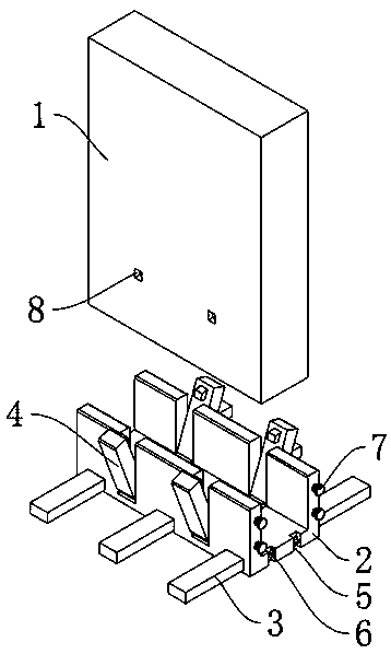
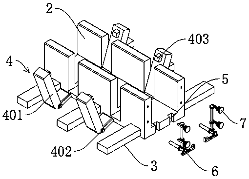
[0027] see Figure 1-3 , a prefabricated building wall component, including a prefabricated wall 1 and a fixed seat 2, the prefabricated wall 1 is arranged on the fixed seat 2, the two sides of the fixed seat 2 are fixedly connected with auxiliary fixing rods 3, the prefabricated The wall 1 is provided with a clamping groove 8, and the fixing seat 2 is connected with a clamping device 4, and the clamping device 4 matches the clamping groove 8; one side of the bottom plate of the fixing seat 2 is provided with a mounting groove 5, and there are 5 mounting grooves A fixed seat connection mechanism 6 is installed, and the side of the fixed seat 2 bottom plate away from the installation groove 5 is fixedly connected with a connecting ear 9, the connecting ear 9 matches the fixed seat connection mechanism 6, and the fixed seat 2 is also connected with a fixed seat locking mechanism 7. The fixing seat locking mechanism 7 is matched with the fixing seat connecting mechanism 6, and th...
Embodiment 2
[0031] see Figure 4-5 , based on Embodiment 1, the difference is that;
[0032] The fixed base connection mechanism 6 includes a first linkage shaft 601, which is rotatably connected to the inside of the fixed base 1, one end of the first linkage shaft 601 is fixedly connected to the connection shaft 402, and the other end is fixedly connected to the first gear 602 , the first gear 602 is meshed with the first connecting rack 603, the first connecting rack 603 is slidingly connected to the bottom plate of the fixed seat 2, the first connecting rack 603 is fixedly connected with a locking rod 604, and the locking rod 604 is connected with Connecting ears 9 match.
[0033] The present invention is provided with a mounting groove 5 on one side of the bottom plate of the fixing seat 2, and a locking rod 604 is installed in the mounting groove 5, and at the same time, a connecting ear 9 is fixedly installed on the fixing seat 2 relative to the side of the mounting groove 5, and t...
Embodiment 3
[0035] refer to Figure 6 ; Based on Embodiment 1 or 2, the difference is that;
[0036] The first bevel gear 605 is also fixedly connected to the first linkage shaft 601, the first bevel gear 605 is meshed with the second bevel gear 606, the second bevel gear 602 is fixedly connected to the bottom end of the second linkage shaft 607, and the second linkage The shaft 607 is rotatably connected inside the fixed base 2 .
[0037] The middle part and the top end of the second linkage shaft 607 are respectively fixedly connected with a second gear 608, and the second gear 608 is engaged with the second connection rack 609, and the second connection rack 609 is slidably connected to the inside of the side plate of the fixed base 2, fixed The seat locking mechanism 7 is connected to the outer end of the second connecting rack 609 .
[0038] The fixing seat locking mechanism 7 includes a connecting rod 701, one end of the connecting rod 701 is fixedly connected with the second conn...
PUM
 Abstract
Description
Claims
Application Information
 - R&D
- Intellectual Property
- Life Sciences
- Materials
- Tech Scout
- Unparalleled Data Quality
- Higher Quality Content
- 60% Fewer Hallucinations
Browse by: Latest US Patents, China's latest patents, Technical Efficacy Thesaurus, Application Domain, Technology Topic, Popular Technical Reports.
© 2025 PatSnap. All rights reserved.Legal|Privacy policy|Modern Slavery Act Transparency Statement|Sitemap|About US| Contact US: help@patsnap.com


